2016
Useful tips from Splice Crimping Seminar: compression – resistance – pull-force. Part 2.
First tests results for the cross-dependence between crimp height, compression, pull force, resistance, different splice band sizes, materials and tooling types. Input data here.
BEFORE THERMOCYCLING
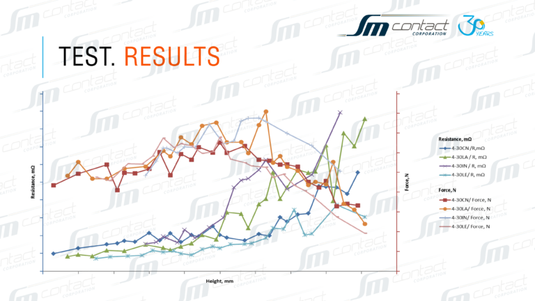
On the base of resistance and pull force measurements the curve was formed to illustrate parameters correlation. Final graph is relevant to the USCAR-21 crimp curve:
- All the results have similar tendency within small deviations because of different splice band materials.
- Compression reduces once the crimp height increases which leads to the gaps between the components. The more gaps there are, the higher resistance is.
- Compression rate for given dimensions depends on the geometry and not on the physical properties of the material.
- Stable zone of resistance doesn’t always correspond to the maximum pull force. Required pull force level has to be reached by the mechanical joining of the components.
- Too tight crimp leads to higher resistance and to the drop of the pull force.
- LE splice band (tinned brass, SN 3-6 μ on nickel 1-3 μ) allows having less compression with good resistance.
- Maximum pull force level is the same for all kinds of the materials.
AFTER THERMOCYCLING
As most of the connections under actual operating conditions are affected by thermal stress, tests were repeated after temperature cycling. Tests’ comparison illustrates different splices’ capacity to retain their properties over appropriate environments conditions range. Parameters cross-dependence example for the case of 2 mm LA and CN splice:
- LA splice band material, CI clincher (rectangular shape)
Small resistance deviation (max. resistance before thermal cycling – 4,42 mOhm, after – 12,90 mOhm).
High crimp damage risk.
- LA splice band material, standard clincher (bell mouth shape)
Big resistance deviation (max. resistance before thermal cycling – 6,46 mOhm, after – 300,00 mOhm).
Less damage risk.
- CN splice band material, standard clincher (bell mouth shape)
Less resistance deviation (max. resistance before thermal cycling – 6,43 mOhm, after – 47,00 mOhm).
Less damage risk.
SOLUTION – OPTIMAL CLINCHER PLATEAU DIMENSION RESEARCH.
Results coming soon.

Resistance – pull force test

Resistance – pull force test
Previous “Useful tips”:
Next “Useful tips”:
- Splice crimping vs. welding
- What do industrial crimp norms say about splice connection?
- IEC 60352-2 international standard as a gate for exotic splices


