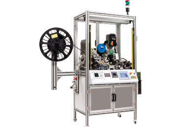
SM Crimp V8 Advanced
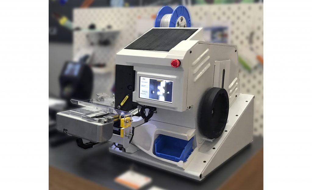
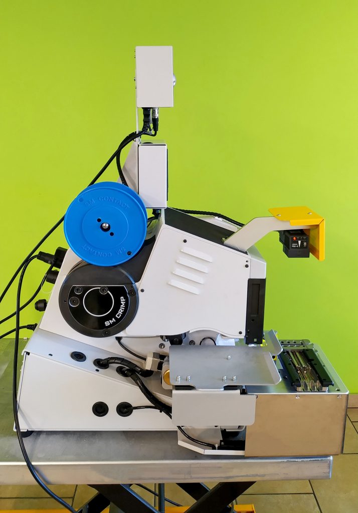

SM Crimp V8 Advanced operation involves components manual positioning to the jig. Each jig is customized to the certain components. Jig is placed in the special support (fixture).
Fixture moves between loading and work positions automatically (by servomotor). These positions are predetermined to guarantee highly reliable connections.
Splice crimping is performed by pressing the pedal or automatically.
Tool cassette can be designed for a wide range of wire cross-sections, e.g. 0.5-1.5 mm2. What is more, changing only the cassette it is possible to perform various connections with the same splice band.
SPECIFICATIONS:
– digital crimp height adjustment with position controlled by encoder
– built-in CFM
– built-in component position video verification
– punch return to zero position by one touch
– using of several jigs for different components in one fixture
– possibility to mount high resolution external camera for components position, presence, colors, etc.
Technical characteristics
| Power supply | 220-240 V (110 V available) / 50 Hz / 2A |
| Absorbed power | approx. 500 watts |
| Motor rating | 300 watts |
| Cycle time | Depends on product |
| Stroke | 35 mm |
| Crimping range | 35 mm |
| Noise level | < 75 dB |
| Weight | 80-90 kg |
| Dimensions (WxDxH) | 375 x 660 x 490 mm |
| CE conformity | ✔ |
| Apave (TÜV) certification | ✔ |

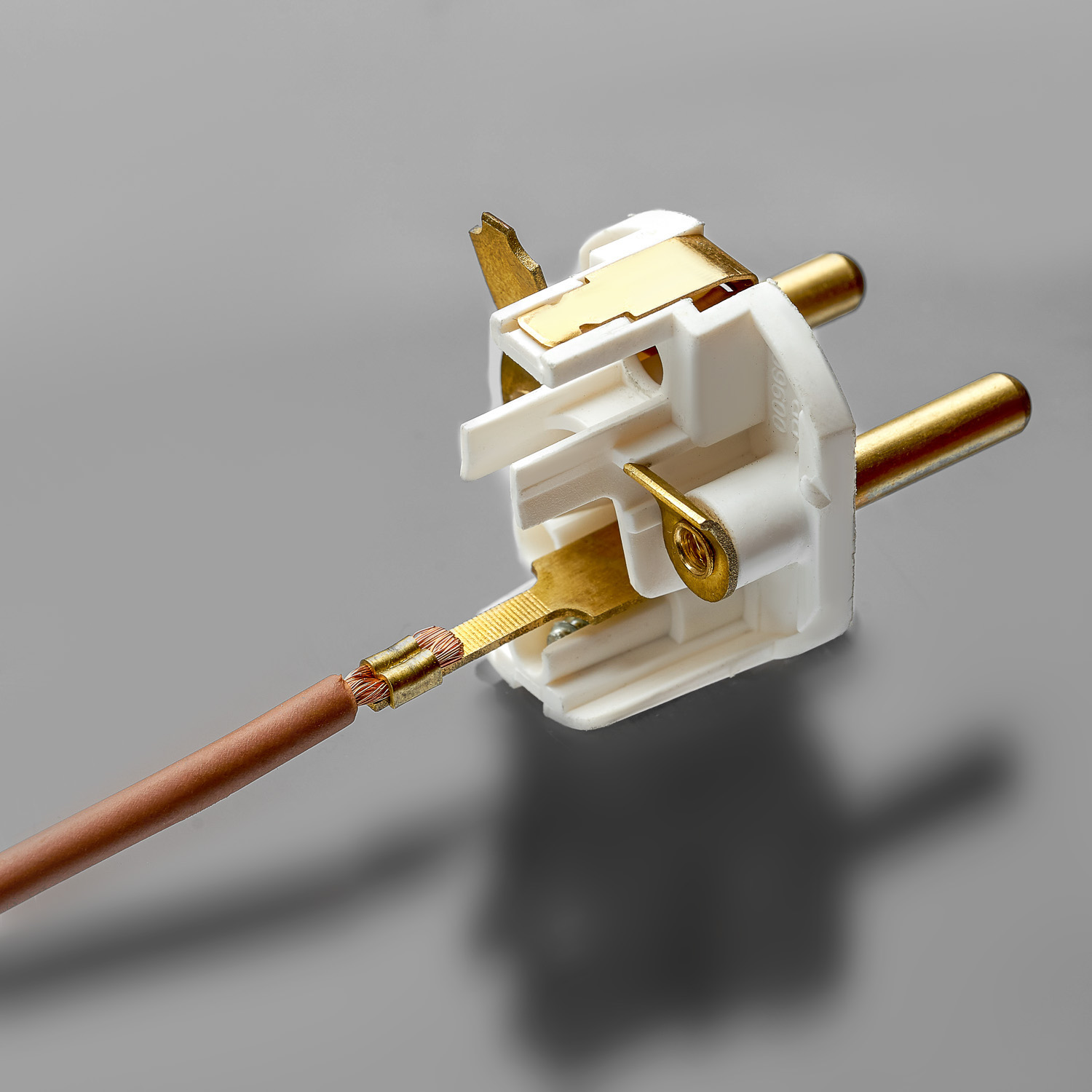
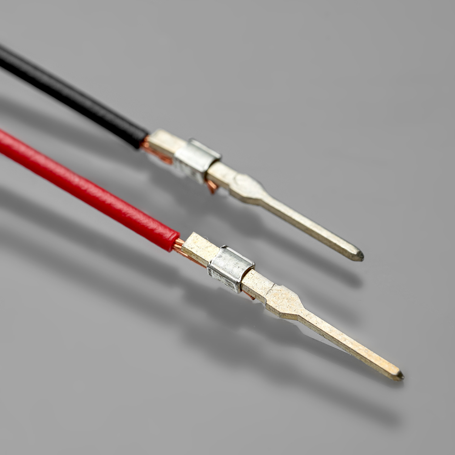
PIN INSERTION
STANDARD FEATURES
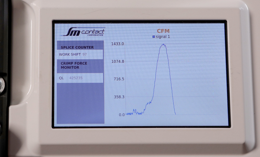
Built-in Crimp Force Monitor (CFM)
CFM captures, calculates and evaluates force-time curve and detects any deviation from the quality tolerances.
System works with many types of splicing and crimping machines and suites well to any application requiring inline monitoring of forces.
The reference curve of CFM corresponds to crimping force, but in fact it can reflect such quality deviations as:
- missing wire strands,
- missing terminal,
- inaccurate components positioning,
- inaccurate crimp height,
- inaccurate wire gauge,
- insufficient insulation strip length,
- insulation in wire barrel,
- wire partially inserted in wire barrel.
CFM allows to adjust automatic cutting and/or rejection of defective items.
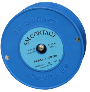
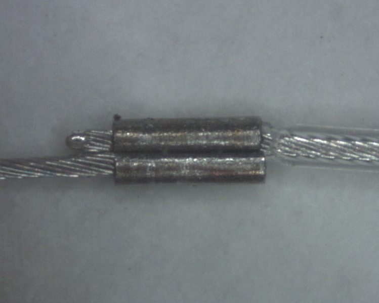
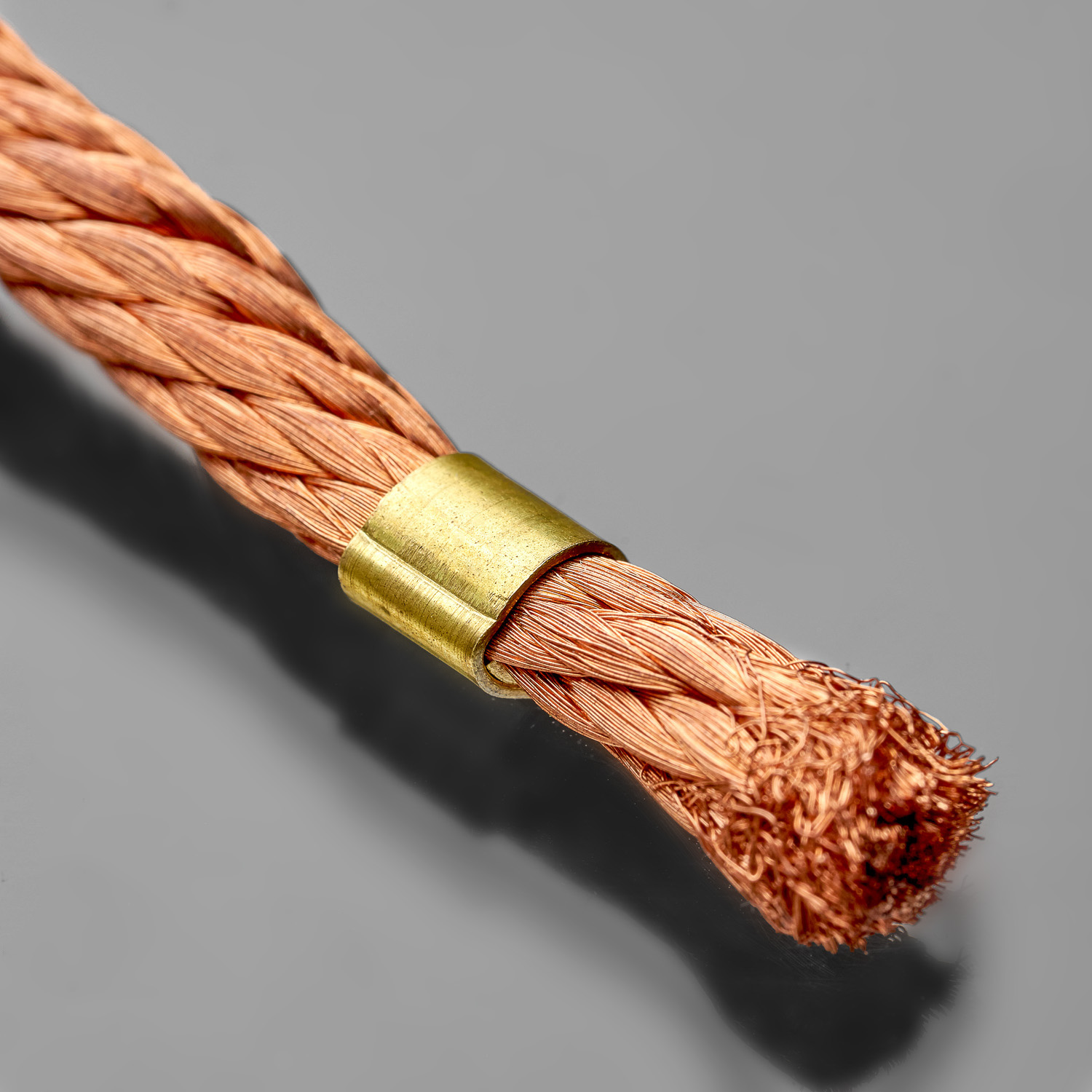
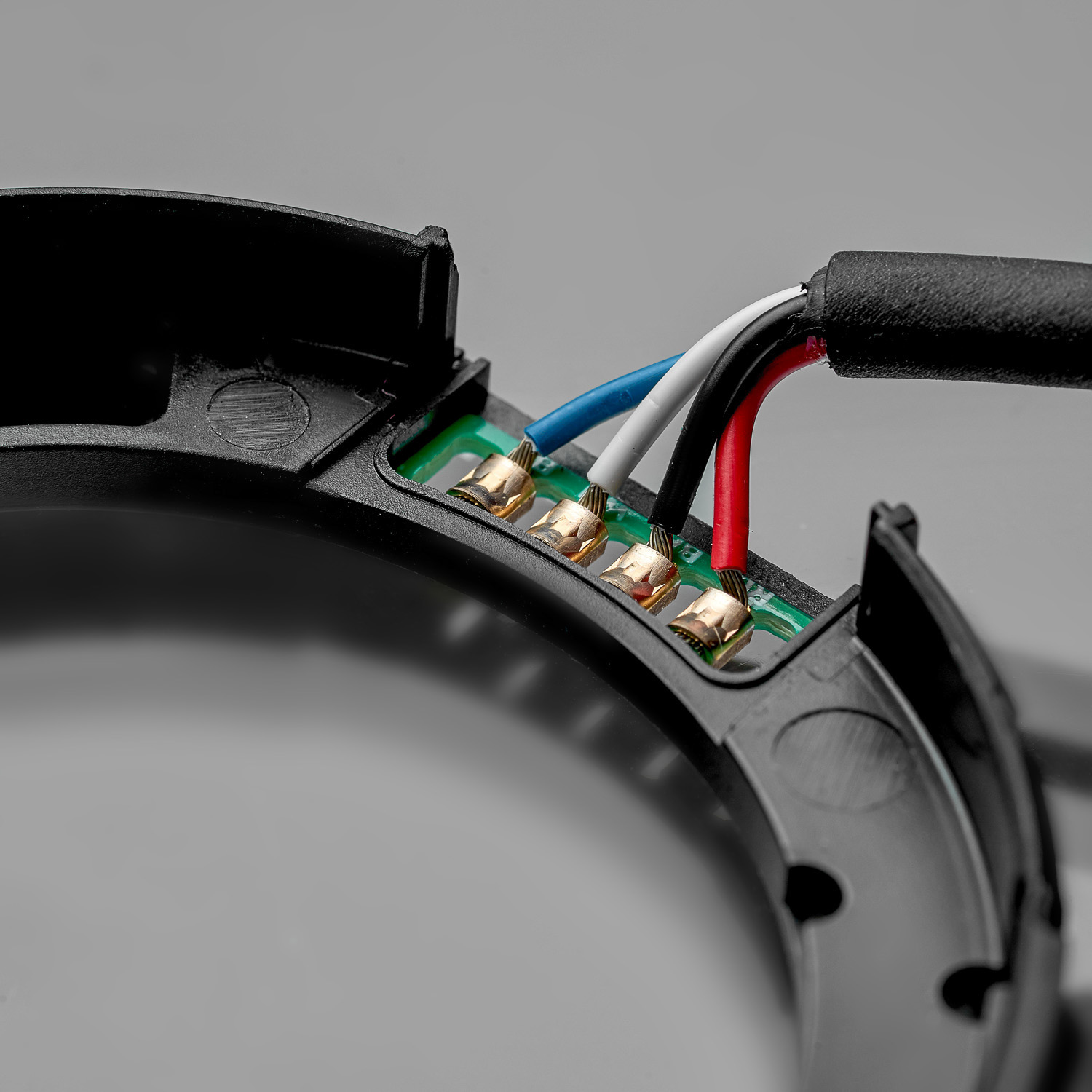
Splice band
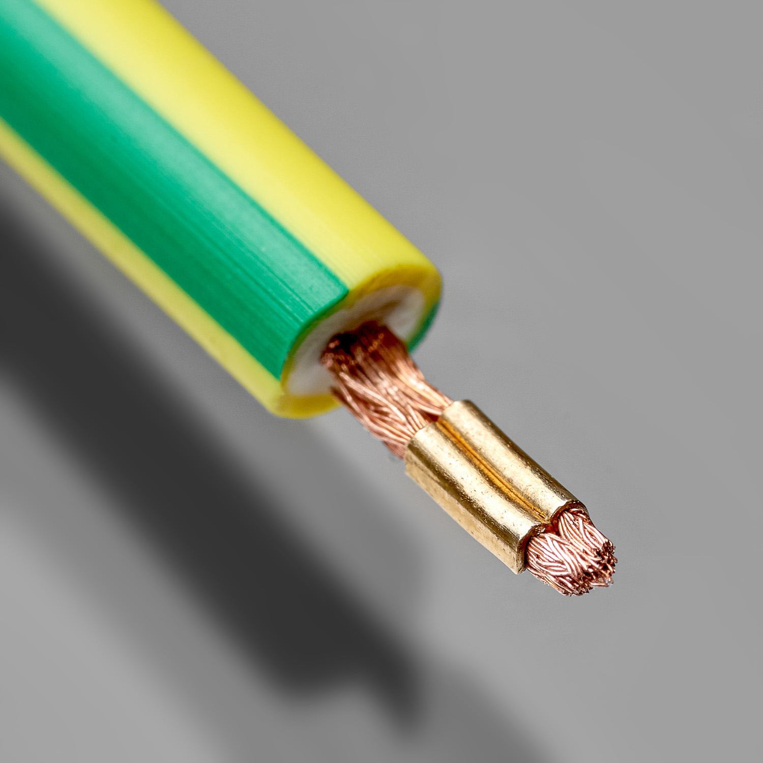
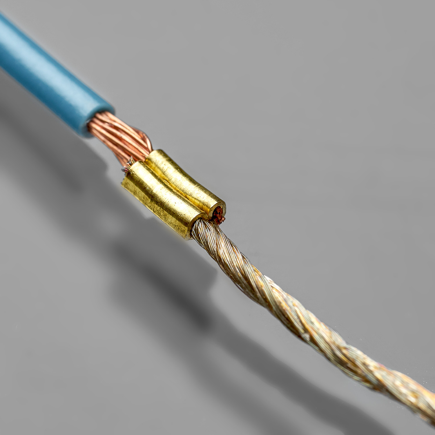
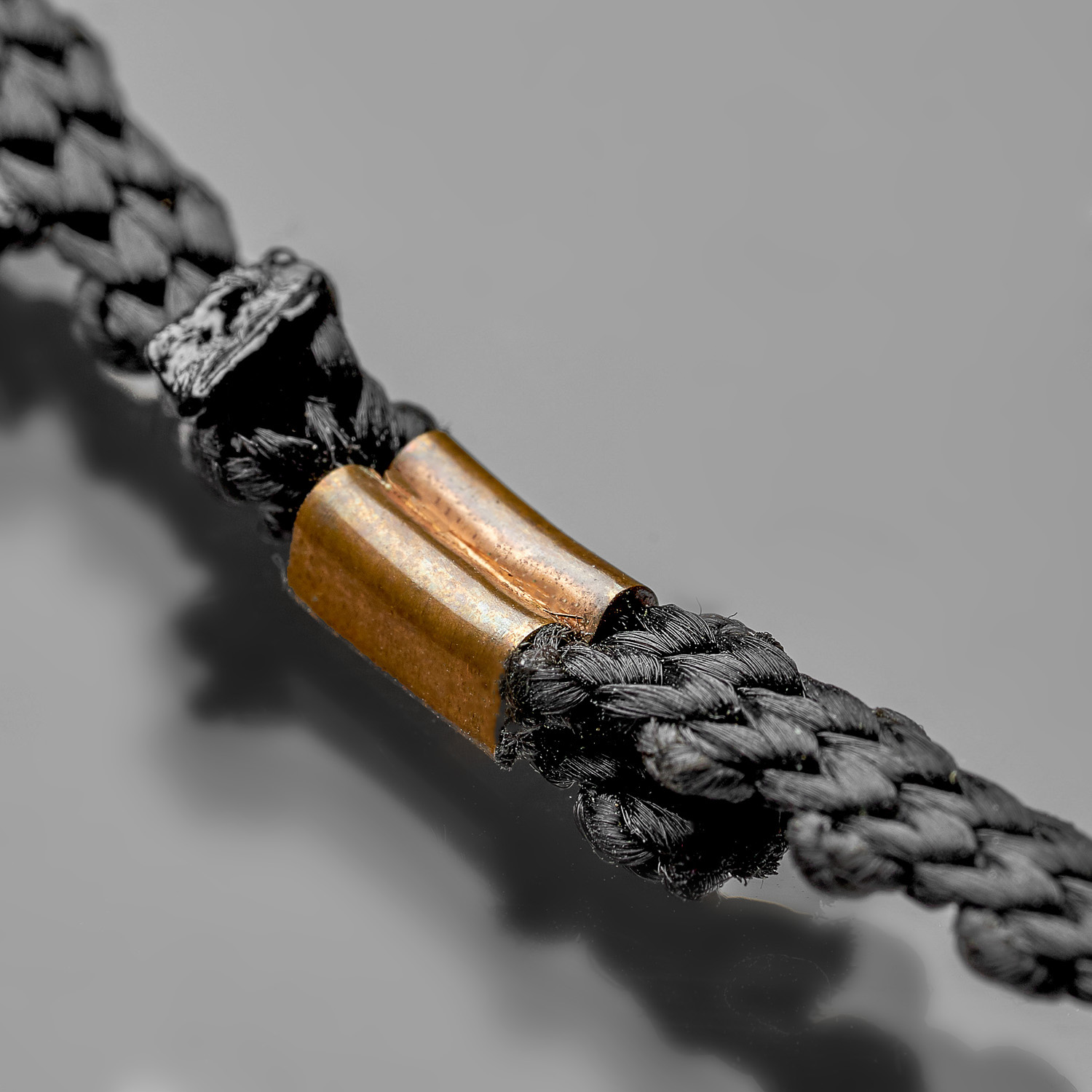
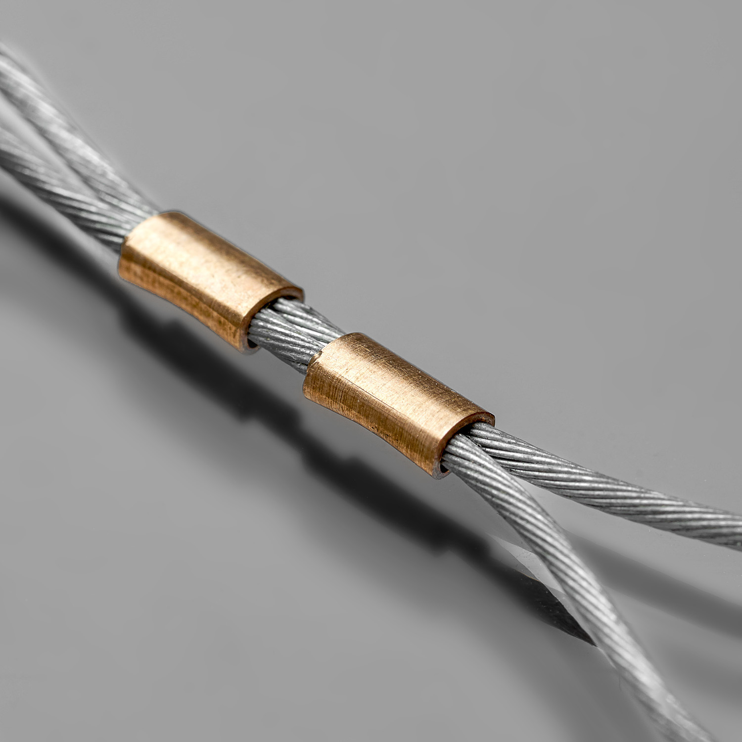
Splice band is defined according to the type of application and environment temperature range: splice band type and material (brass, brass with tin coating, cupronickel,cupronickel with tin coating, stainless steel), thickness (0.2 – 0.53 mm), width (1.5, 2, 3, 4, 6, 7 mm), and length.
Splice band is engineered with serrations for magnet wire and standard wire types. It is suitable for multi-strand and solid core copper and aluminum wires.
Our splice materials meet the following standards:
- UL 486C
- MIL – STD 202
- IEC 60352-2
- IPC/WHMA-A -620
- REACH & RoHS
| SPLICE MATERIAL | APPLICATION |
| Brass CuZn30 | General purpose, -80..+120°C |
| Brass with tin coating CuZn30 tinned | General purpose, -80..+120°C, corrosion resistant, pre-soldered components |
| Cupronickel CuNi9Sn2 | High reliability, -80..+400°C, perfect corrosion resistant, weldable |
| Cupronickel with tin coating CuNi9Sn2 tinned | High reliability, -80..+120°C, perfect corrosion resistant, weldable |
| Stainless steel 2 mm: 2.4867, 4.6 mm: 1.4567 | Special purpose, -80..+900°C, for aggressive environments |
| Customer specified | On request |

Crimp height adjustment
Motorized crimp height adjustment is realized via touch screen with buttons +- (increment of 0.01 mm) or by selecting among preadjusted connections parameters (automatically).

Motorized splice band feeding system
Rubber surface of a feeding wheel prevents damages of the splice band. Special sensor controls the length of each splice.
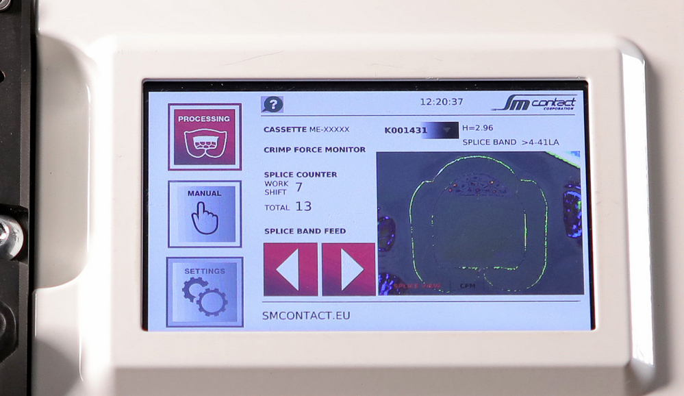
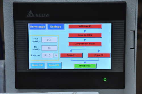
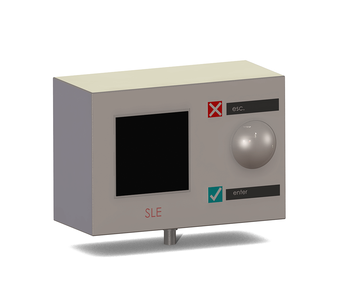
Touch screen control panel
All controls except the power switch are located at the display. With 5 buttons and 1 display it is possible to control the quantity of products, inputs and outputs, interface language, tooling technical data, feeding system and activate emergency stop.
It indicates the process of each crimp in a jig.
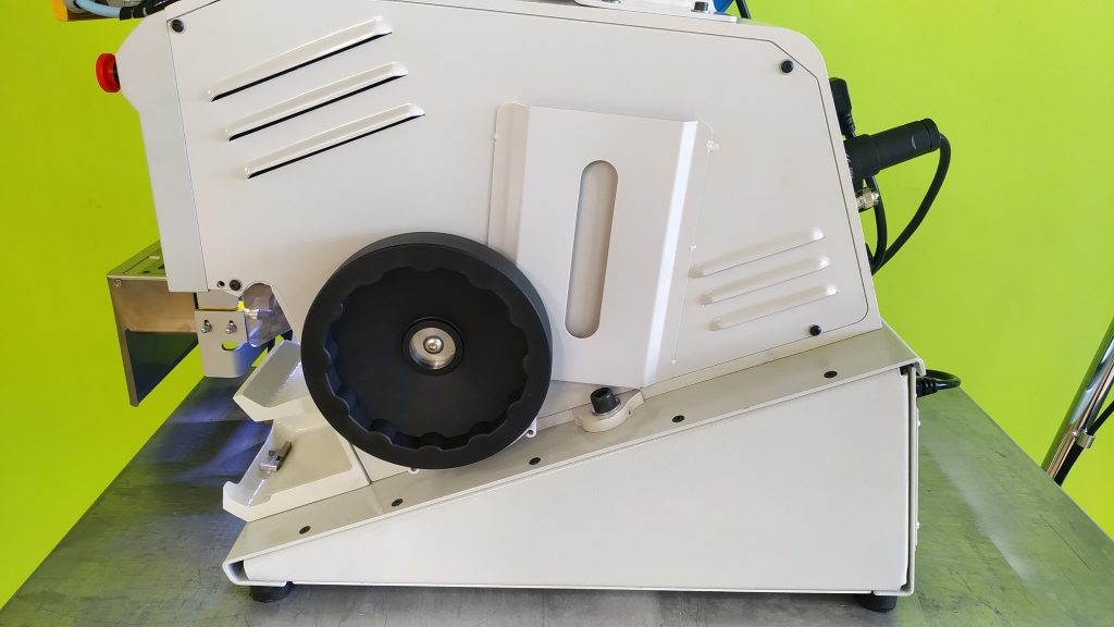
Hand wheel
Hand wheel is used to perform manual cycle for testing the system before production, i.e. centering the clincher, change of tooling. Wheeling moves the punch down and allows to monitor splicing process in general as well as positioning of the tooling.
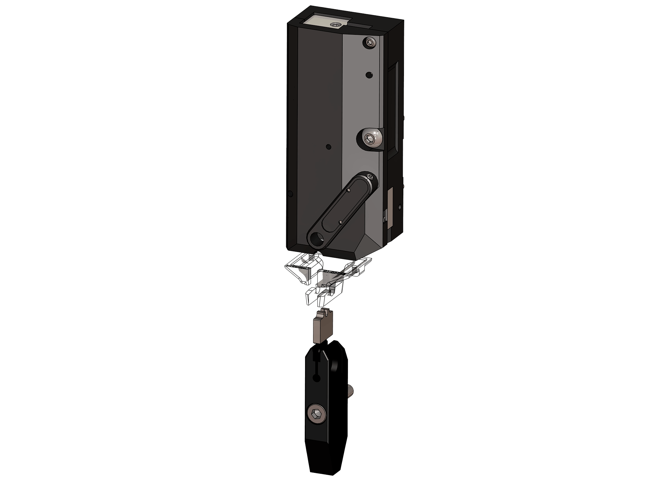
Crimping tooling set
Tooling set includes clincher, anvil, punch, punch guide, and cutting block.
Such parameters as clincher type, clincher size, and punch tip shape are customized for the application.
Inclined clincher surface, smooth cutting surface, quick-change tooling cassette, and finger guard lighting cap guarantees efficient & safe operation.
Data memory in each tooling cassette stores its own tooling list (PN’s) and connection data for up to 10 connections with independent crimp height settings. It enables automatic correction of crimp height when the cassette is installed.
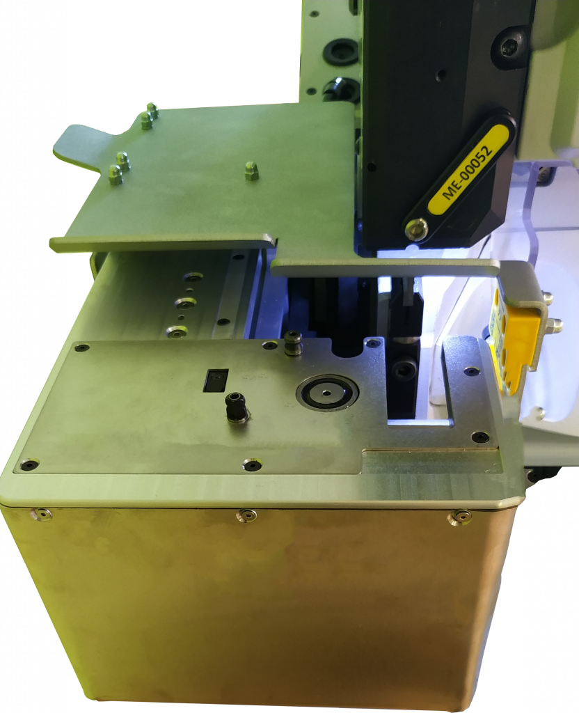
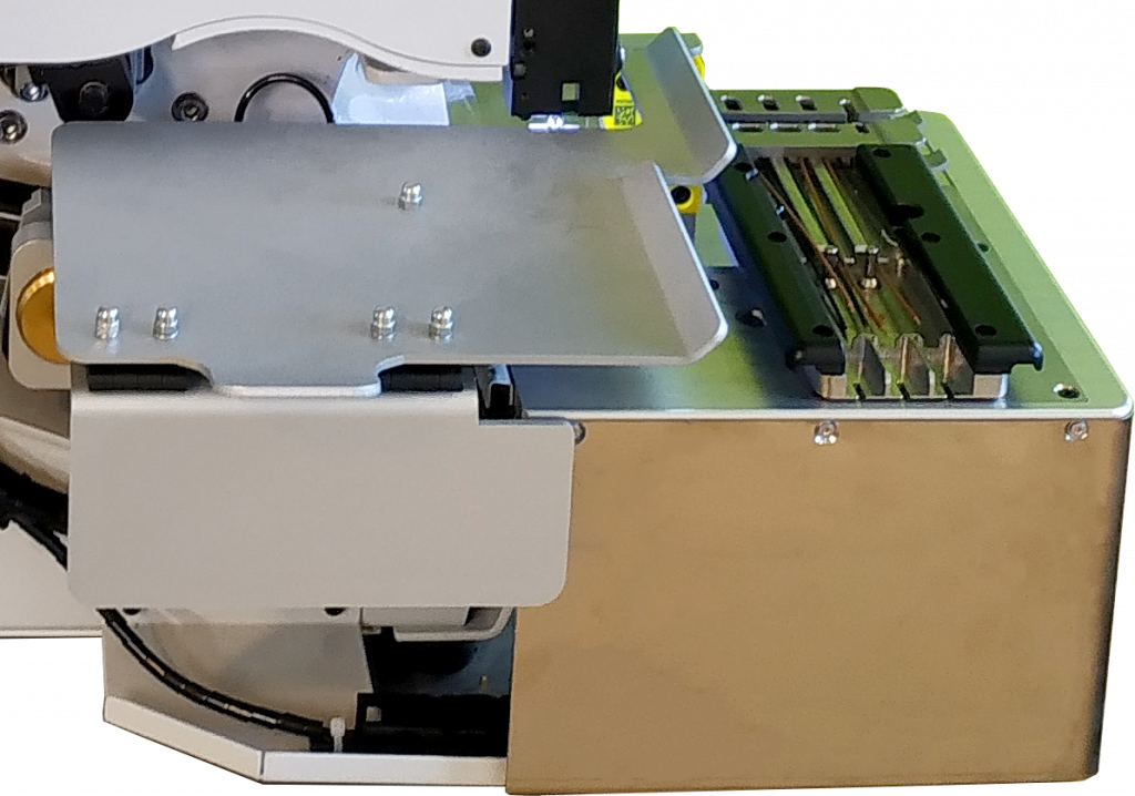
Automated YZ fixture table
Enables shifting the jig with components to the zone of crimping with Y and Z axes capability. High movement accuracy is achieved through programmable actions. Control over the YZ table is provided at the HMI screen, including control of stepper motor drives of the table.
Operator is protected by safety covers.
Support for the jig precisely carries the jig to the crimping zone.
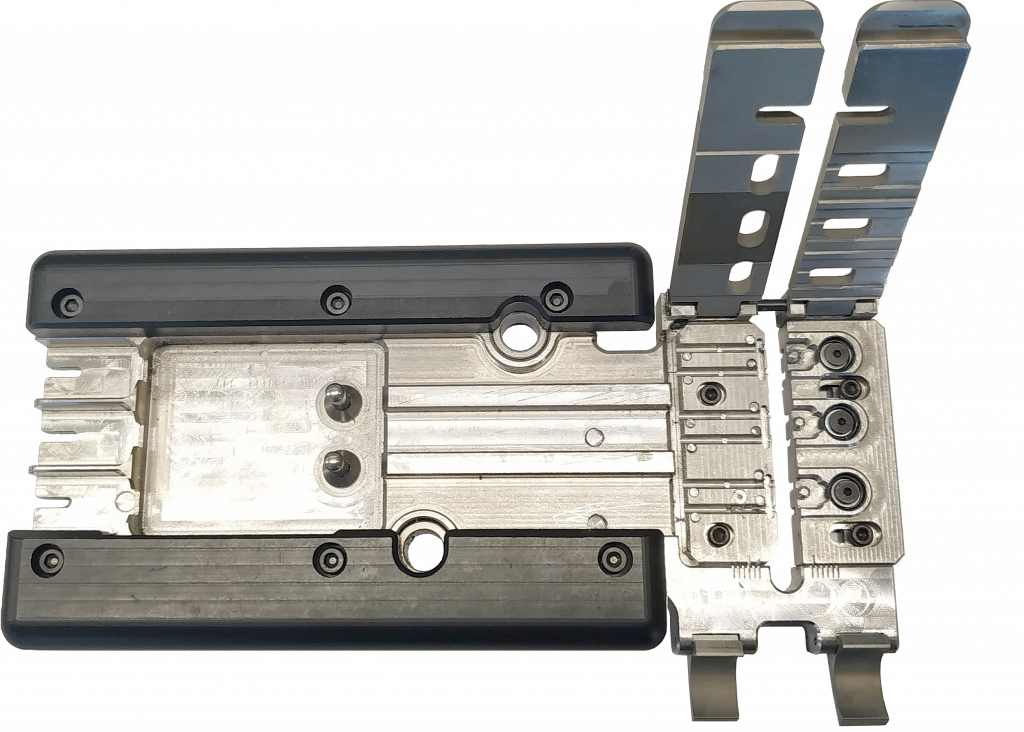
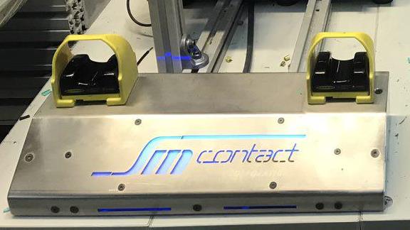
Jig
Removable part of a fixture that perfectly fits components and thus enables its precise positioning. Jig can be adapted to components depending on its quantity, shape, materials.
If machine has two jigs, while one is processing, second can be reloaded by another operator.
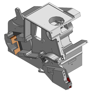
Cast iron frame
In contrast to the machines assembled from separate parts by screws, SM Crimp cast iron frame warrants a perfect stability during crimping.
OPTIONS
HMI
On the touch screen display HMI system shows complete work algorithm, indicating the current step and step when the failure occurred if any. It can be displayed as an algorithm graphics or product visualization.
HMI provides intuitive process control. It is possible to readjust all sensors including CFM to another product by choosing the corresponding program in the interface. HMI displays pictures of connections kept in memory when the tooling cassette is installed and the corresponding connection selected for processing.
Within the password protected area one can switch machine subfunctions on/off. Different access levels (operator and technician) are available at HMI touch screen.
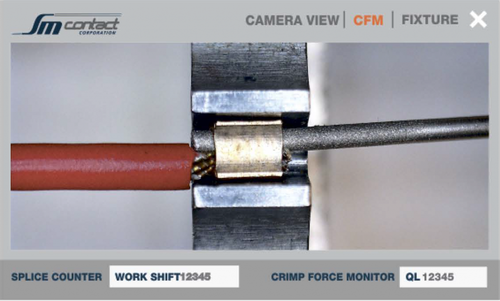
Component position video verification
Camera shoots the clincher area and sends video to the HMI screen in real time. Thus, operator can view the components being crimped and is capable to position them in the clincher precisely.
There are two options for the camera placement:
1, built into the tooling cassette,
2, mounted on the left wall of the tooling cassette and connected via USB cable.
Protection of operation area
Safety covers can be installed on the side panels to detect foreign object presence and stop the machine.
Bimanual cycle start
Requires two hands touch to start the cycle to eliminate hands presence in the work zone.

POKA YOKE
Allows controlling utilization of NG/NOK components. If CFM detects quality deviation and estimates connection as NG/NOK, then machine stops operation and waits until NG/NOK component is placed to POKA YOKE bin.
Components camera control
According to the selected program, high/low definition camera takes pictures and controls components` presense, position, color and stripping length. High or low definition is selected depending on size of components.
Force sensor for CFM
Piezo sensor detects force at the moment of splicing, transmits information to CFM for data processing and displaying force-time curve corresponding to crimp force.
Frame & cabinet
Machine and all its components can be integrated into the floor mount frame for products needs.
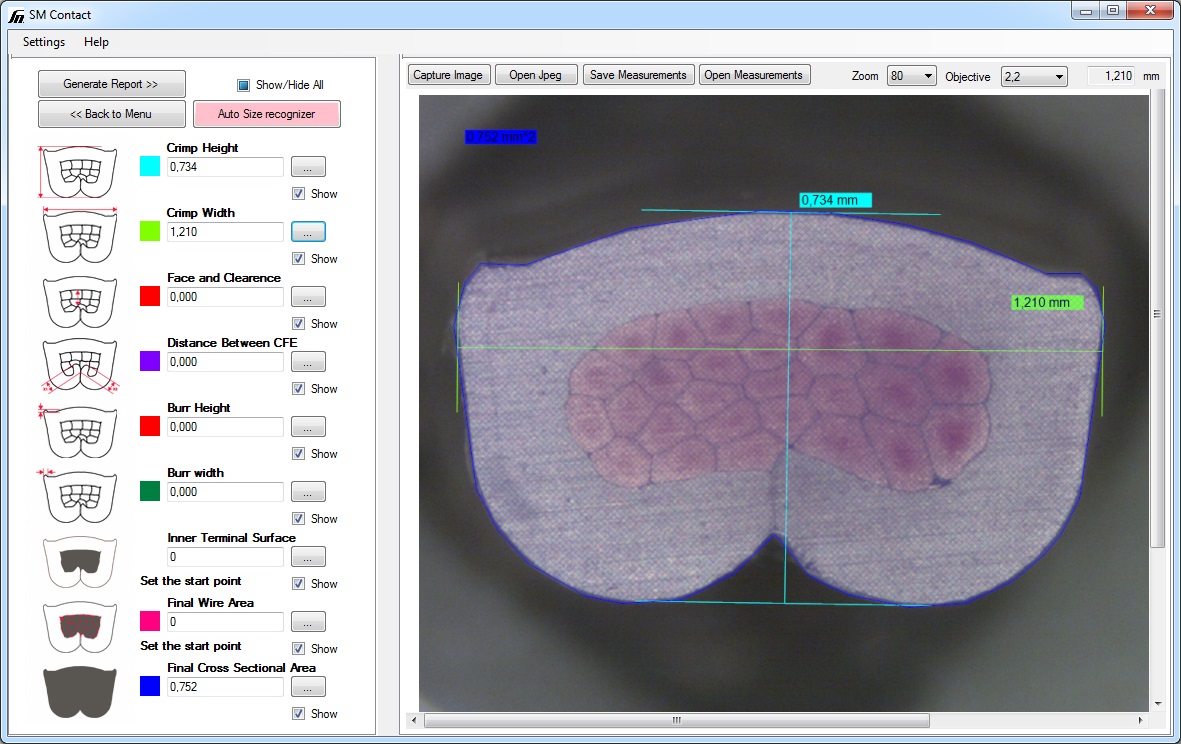
Quality control equipment
Laboratory equipment allows to control whether the splice quality matches industry norms or any other special requirements. Check our micrograph laboratories, pull force and crimp height control tools, as well as specialized measurement software.
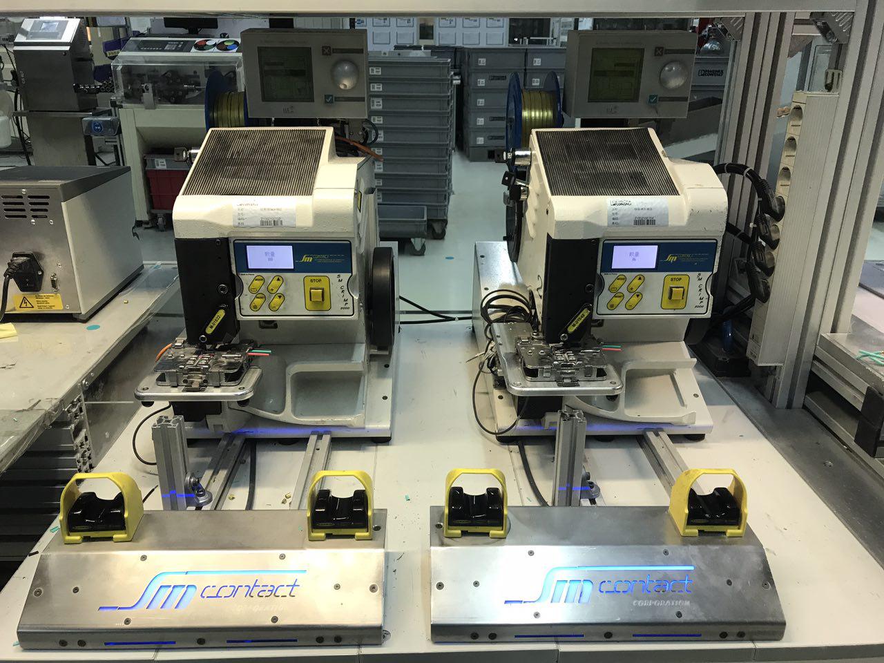
Double crimping
Two machines are used: one set up for one splicing type, another – for the second. This solution speeds up the process and perfectly fits if the product consists of different sized crimping.
ALTERNATIVE ENERGY
AUTOMOTIVE
CIVIL ENGINEERING
ELECTRONICS
LIGHT INDUSTRY
MASS MARKET
MEDICAL
RAILWAY
CORDS
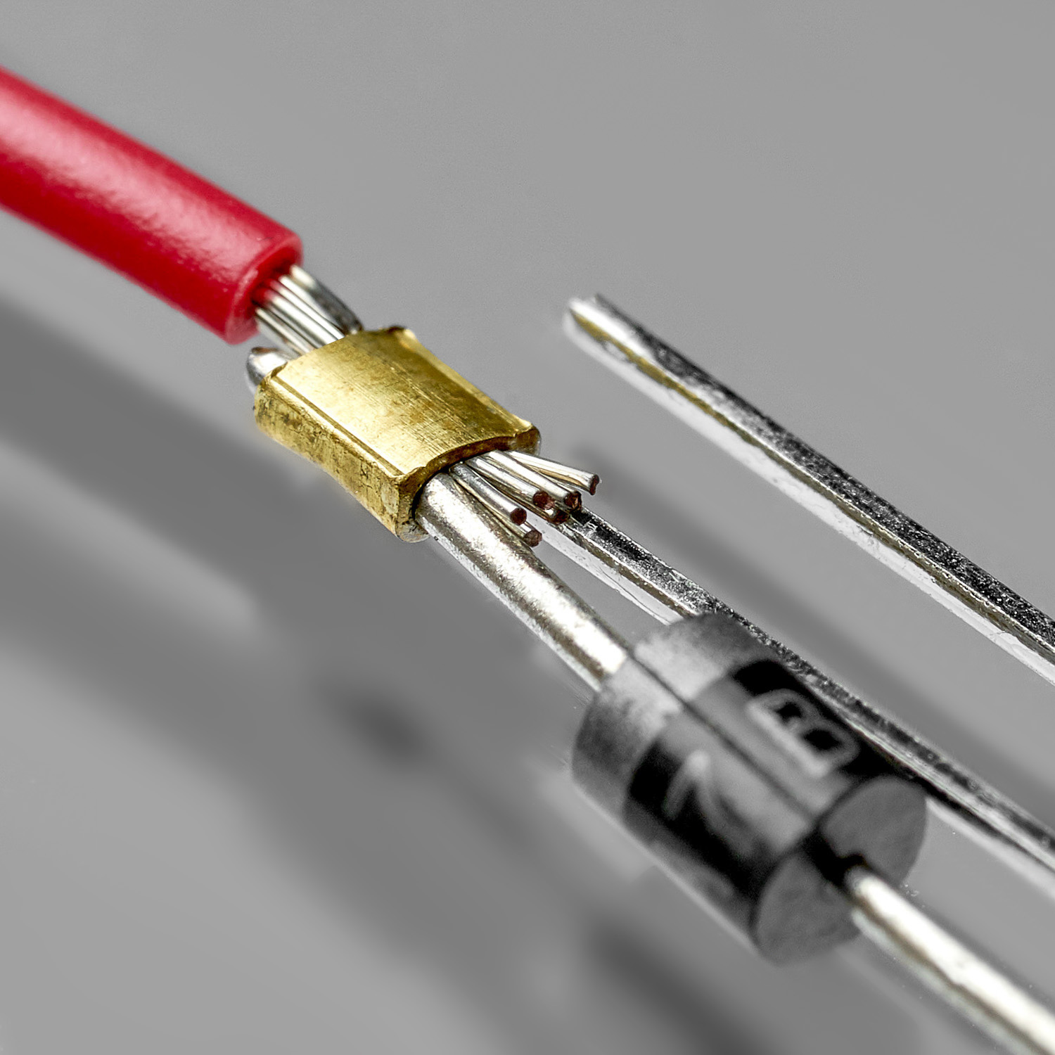
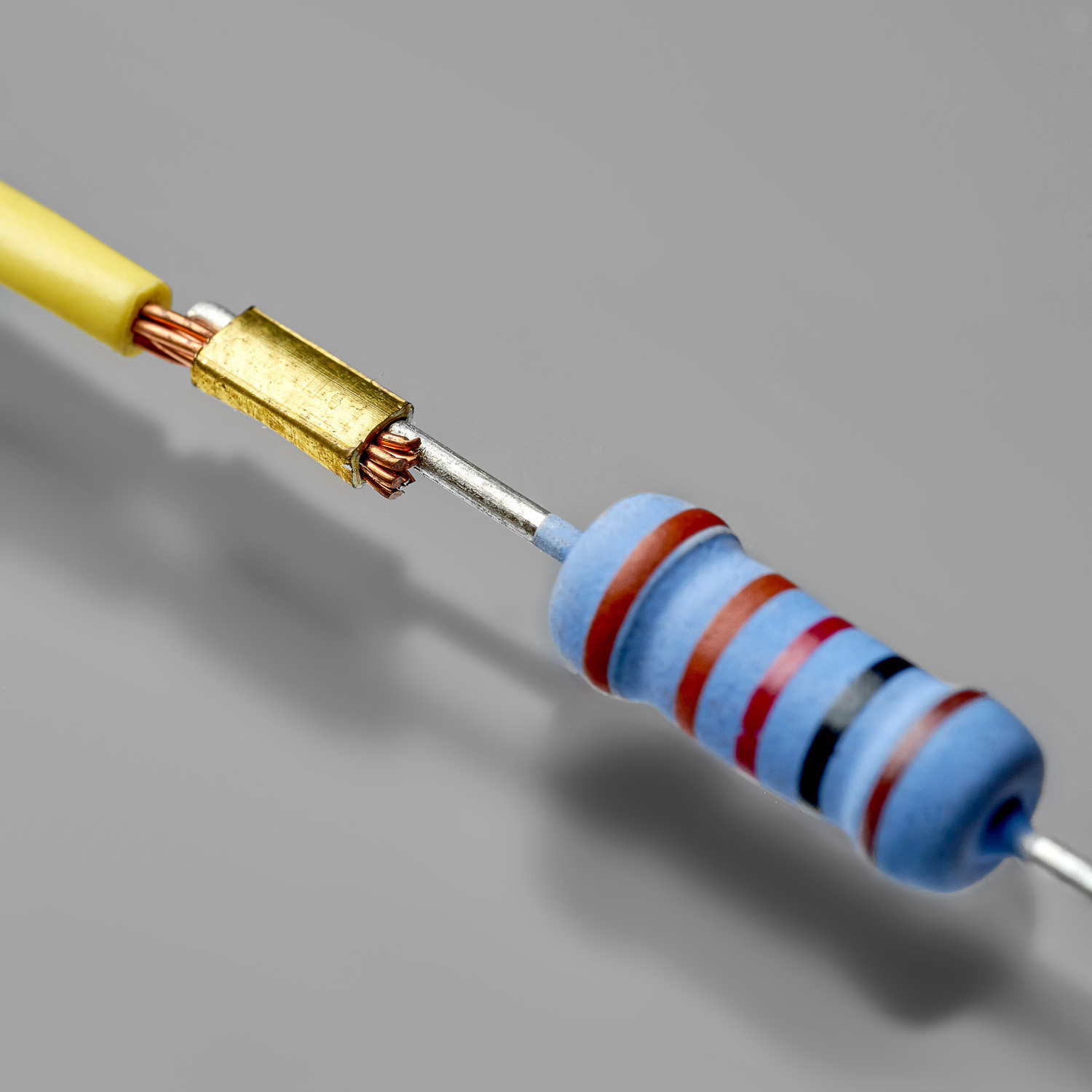
DIODE & RESISTOR
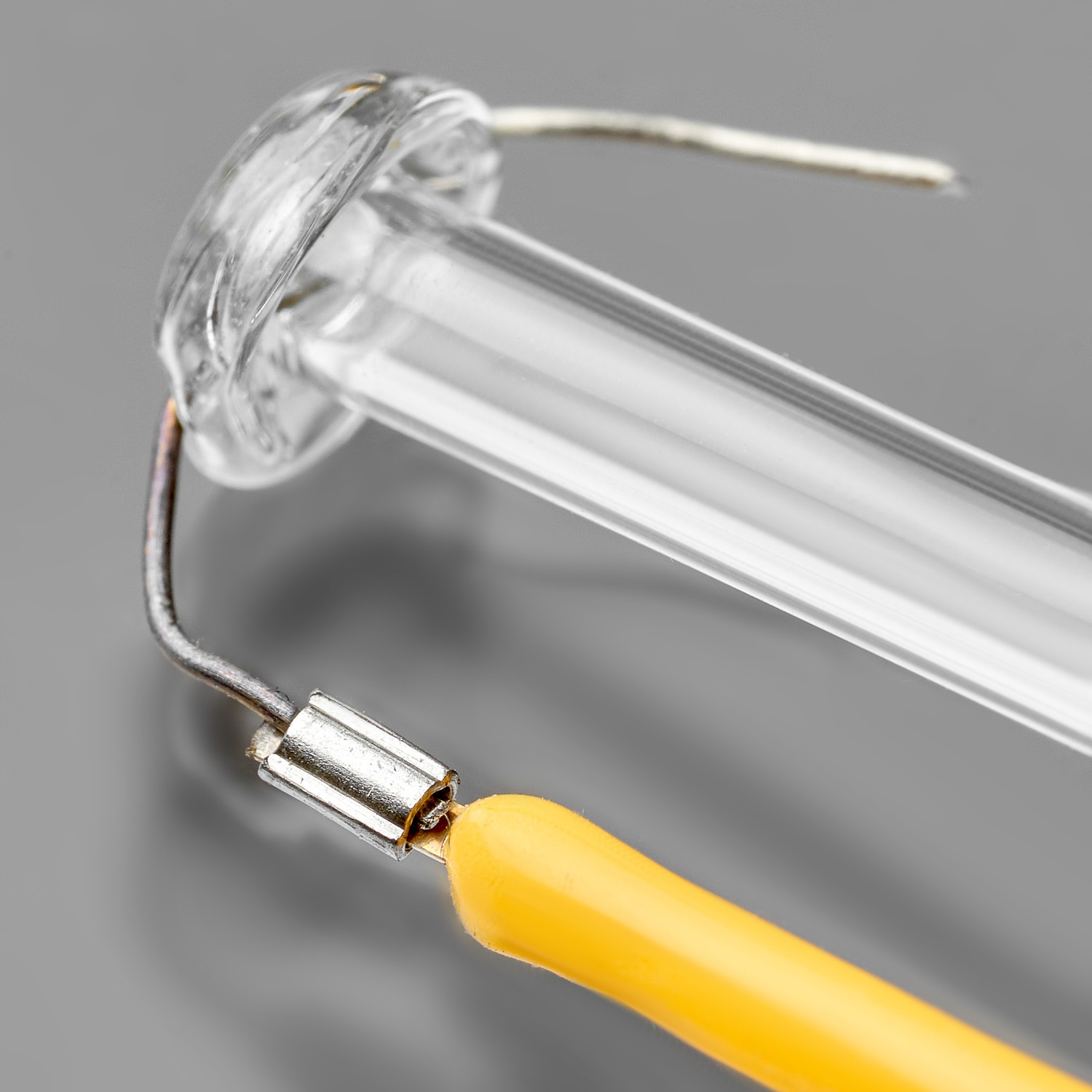
FILAMENT
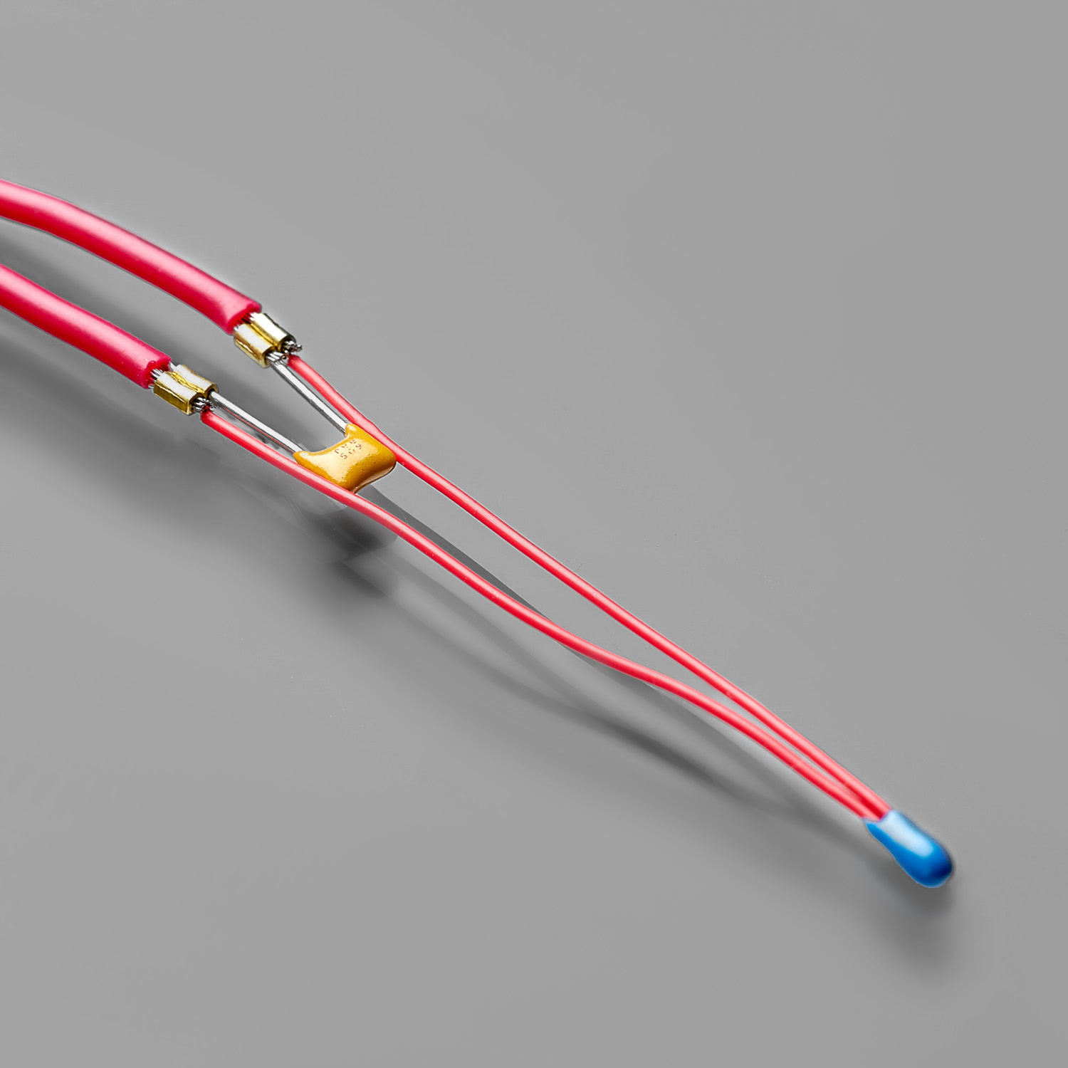
WIRE & CAPACITOR
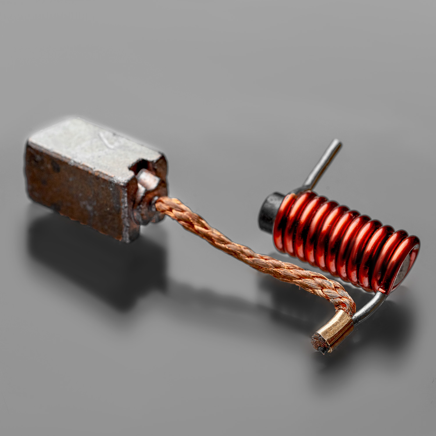
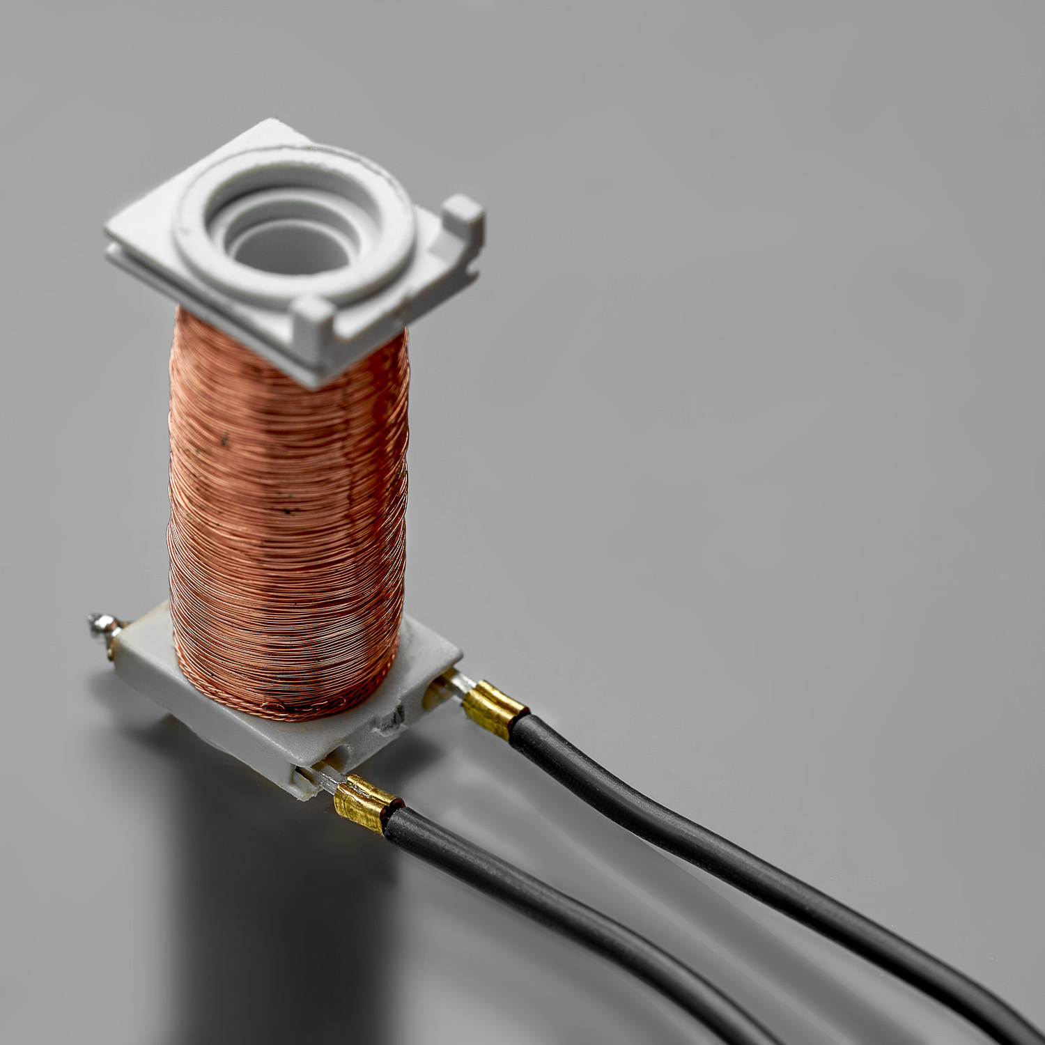
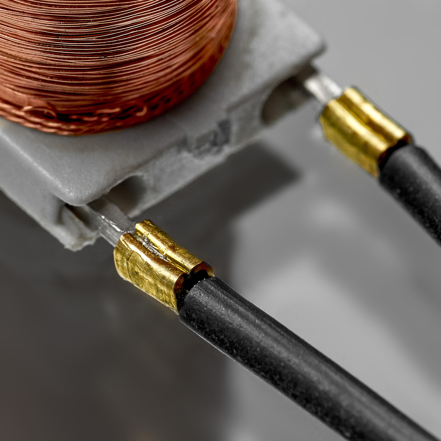
WIRE & COIL
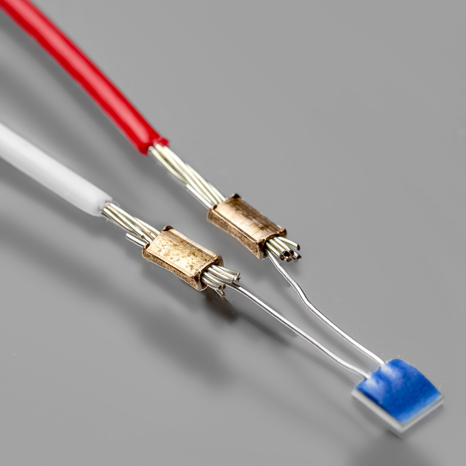
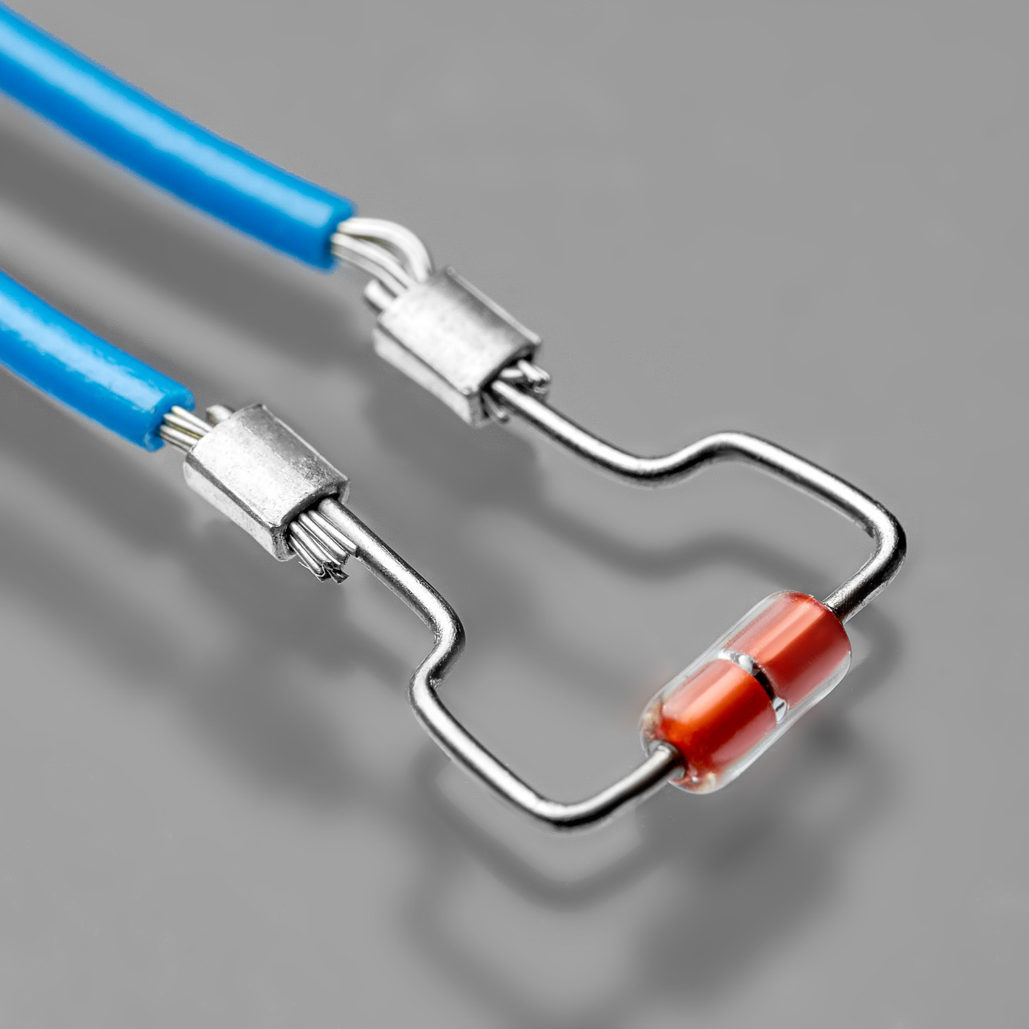
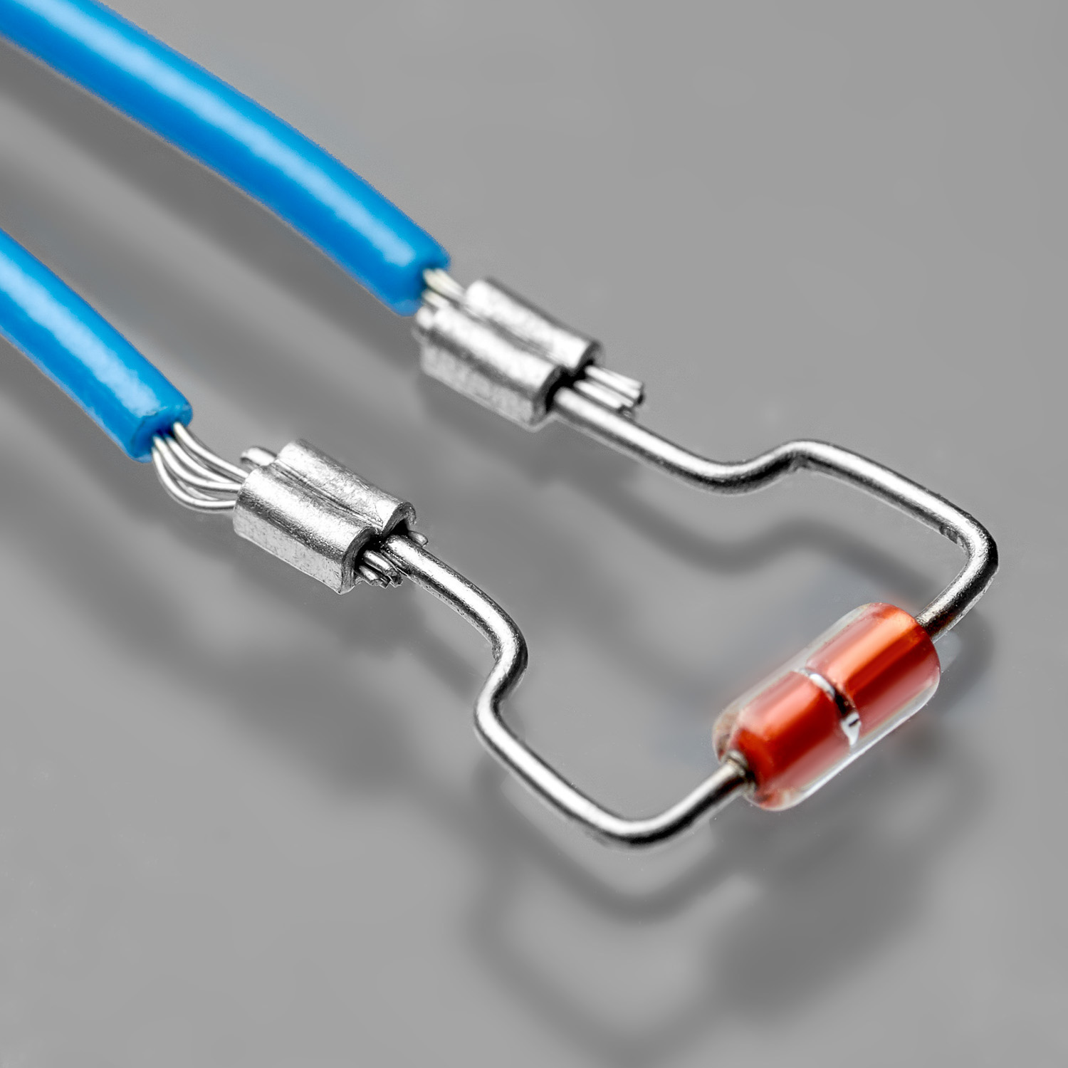
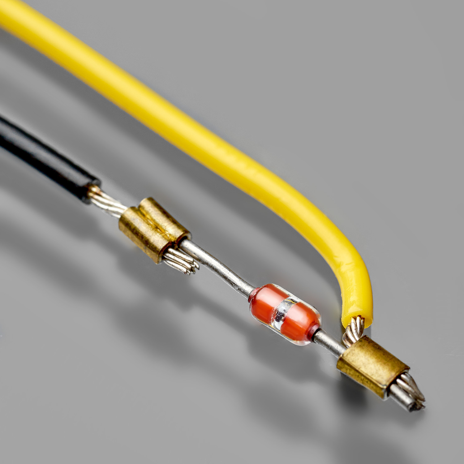
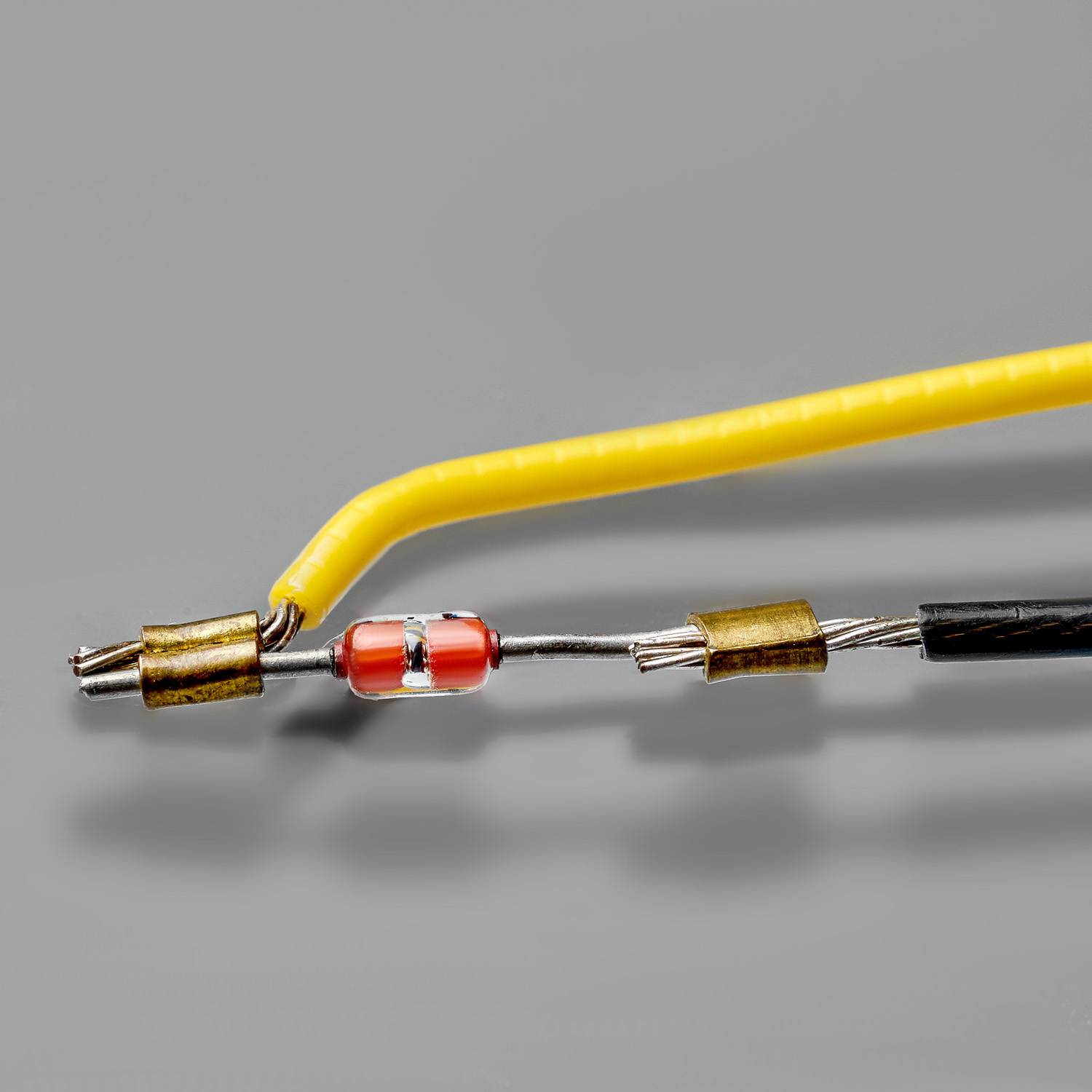
WIRE & DIODE
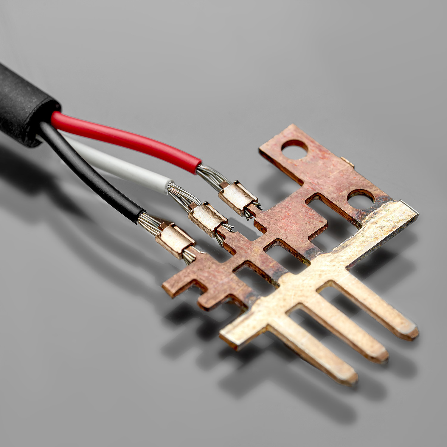
WIRE & LEADFRAME
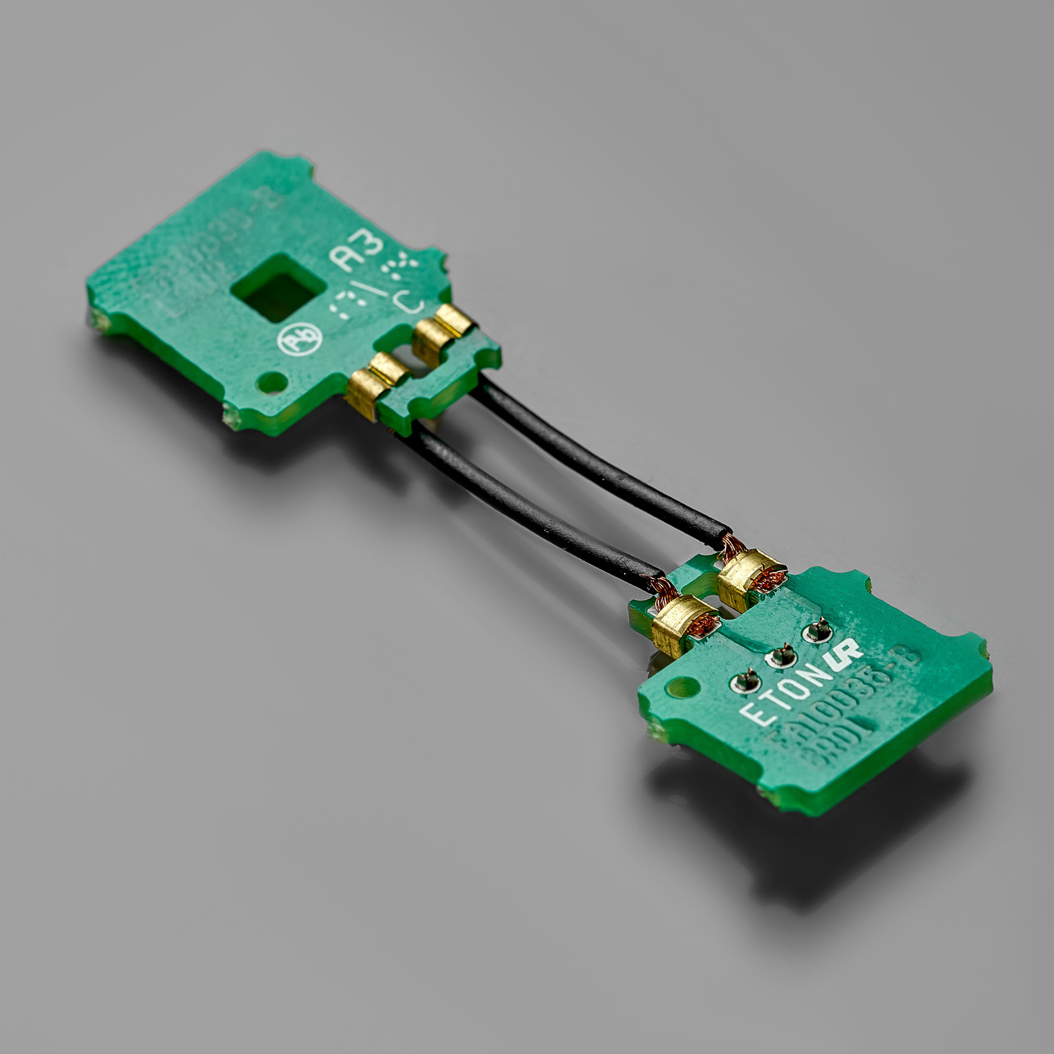
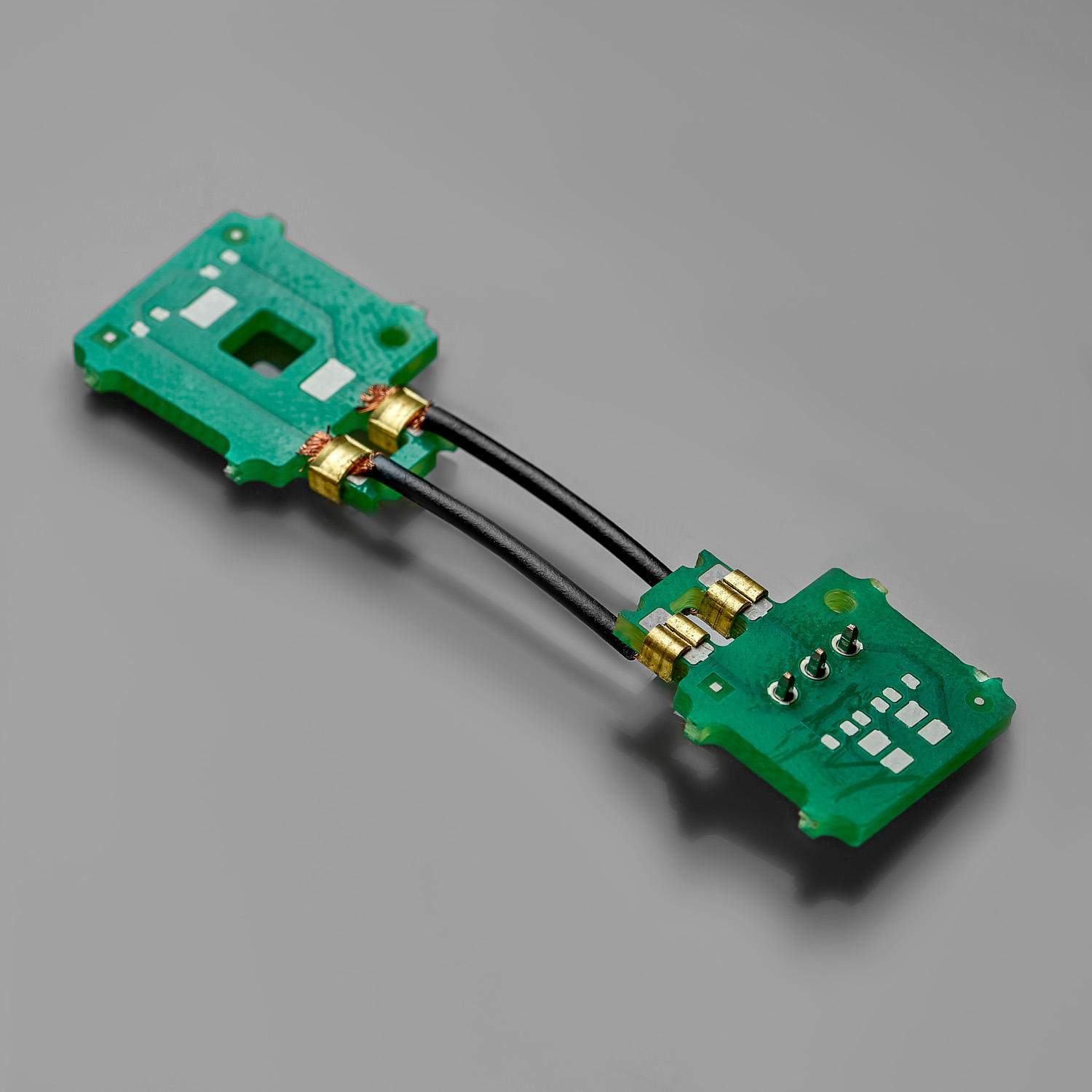
WIRE & PCB
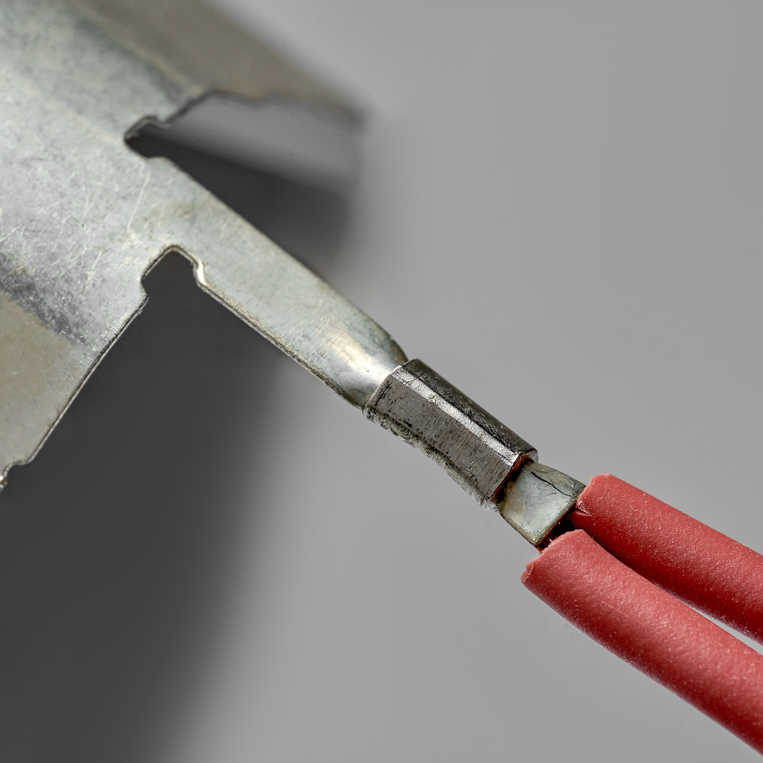
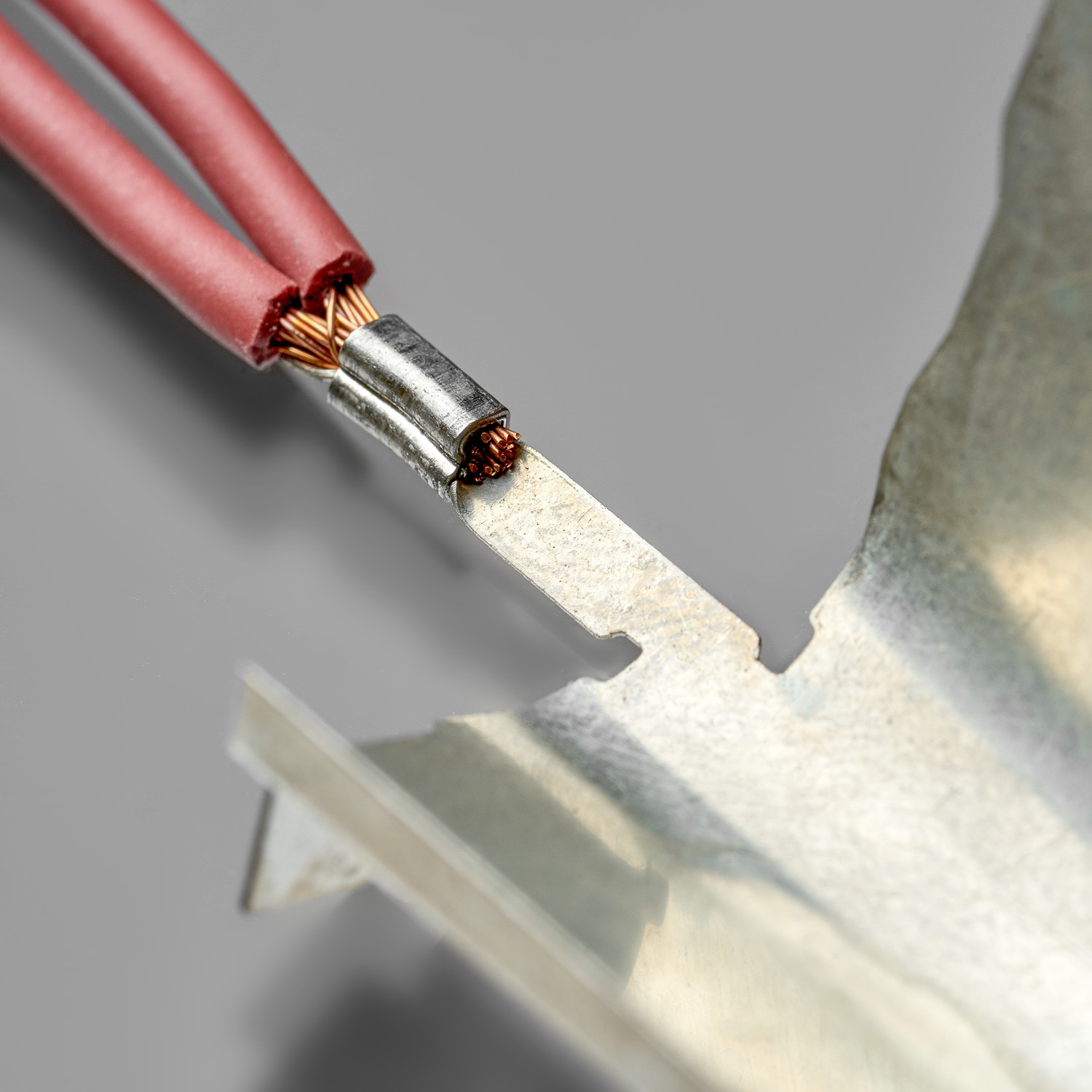
WIRE & METAL TAB
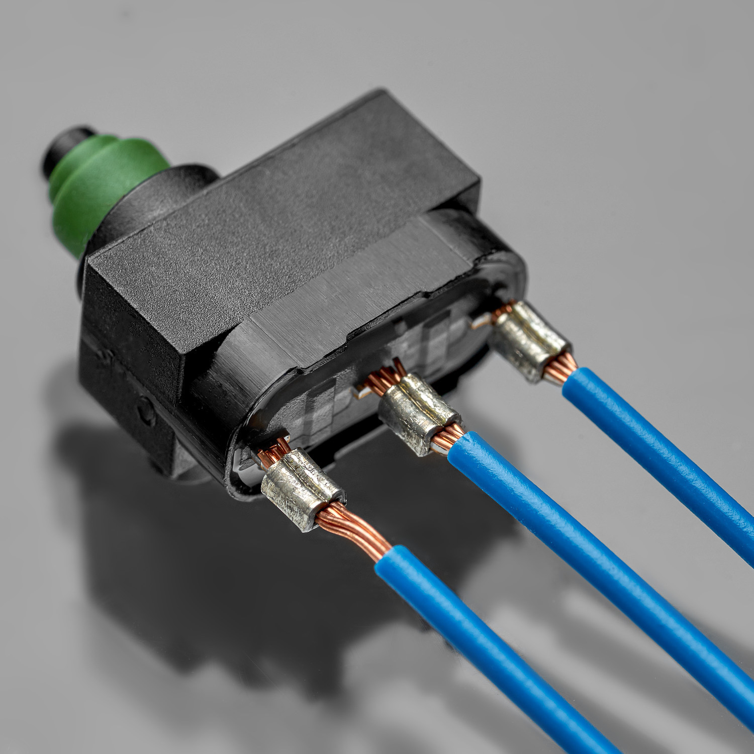
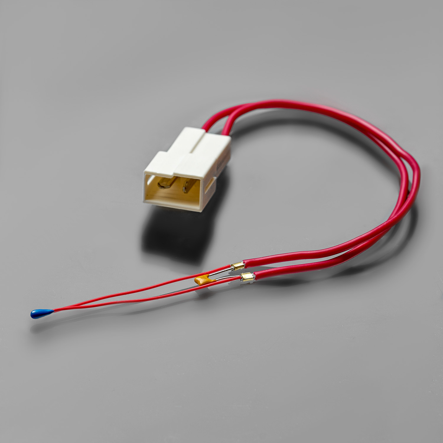
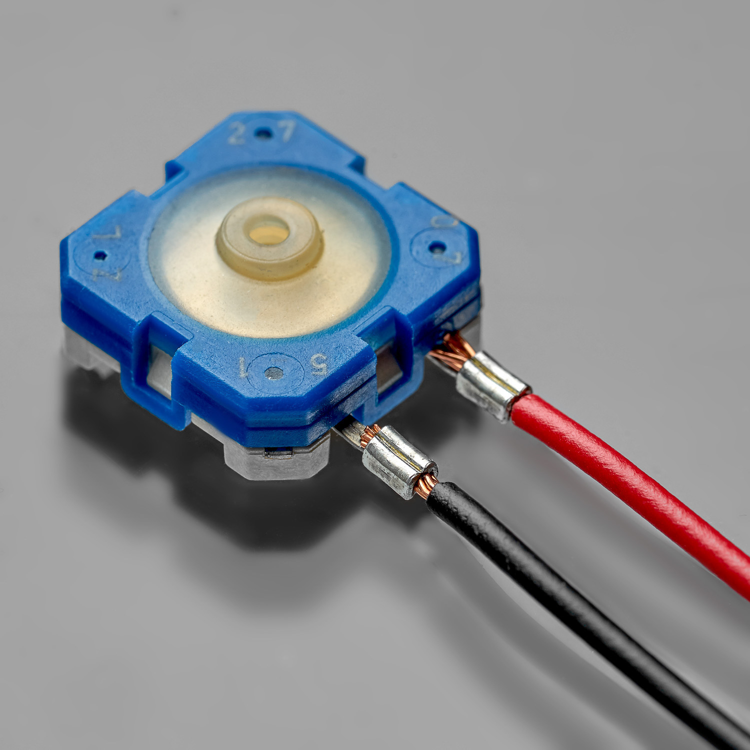
WIRE & SENSOR
WIRE & METAL TAB
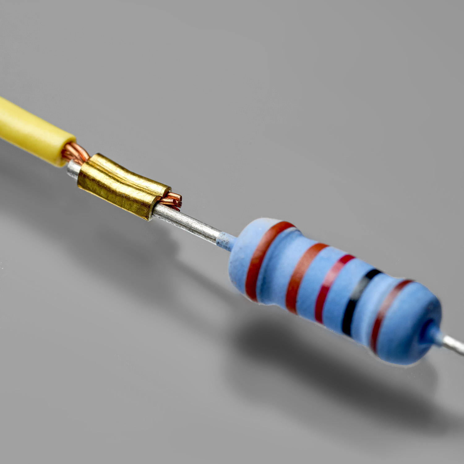
WIRE & RESISTOR
WIRE & METAL TAB
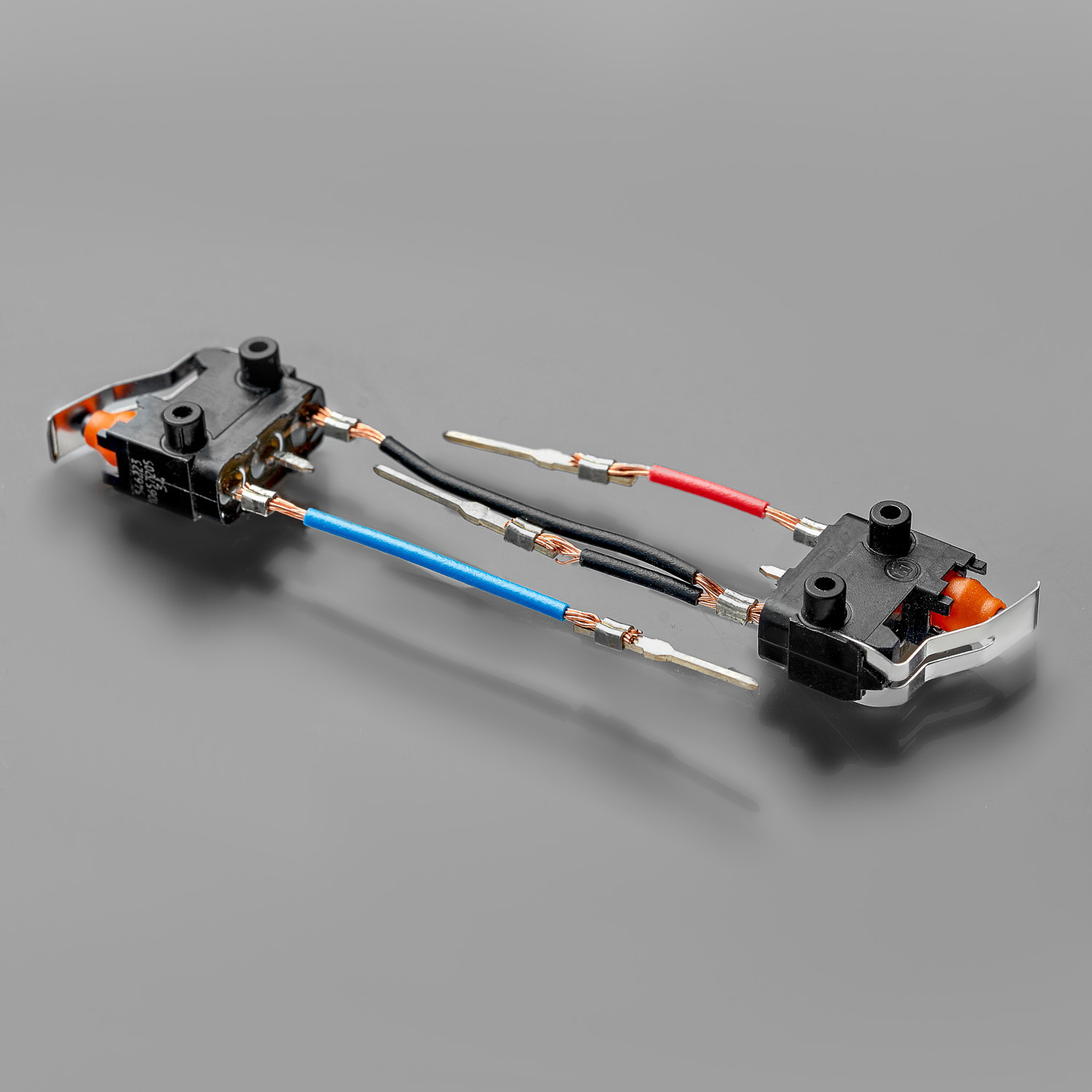
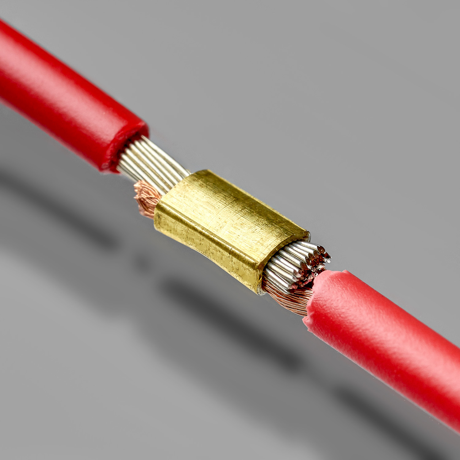
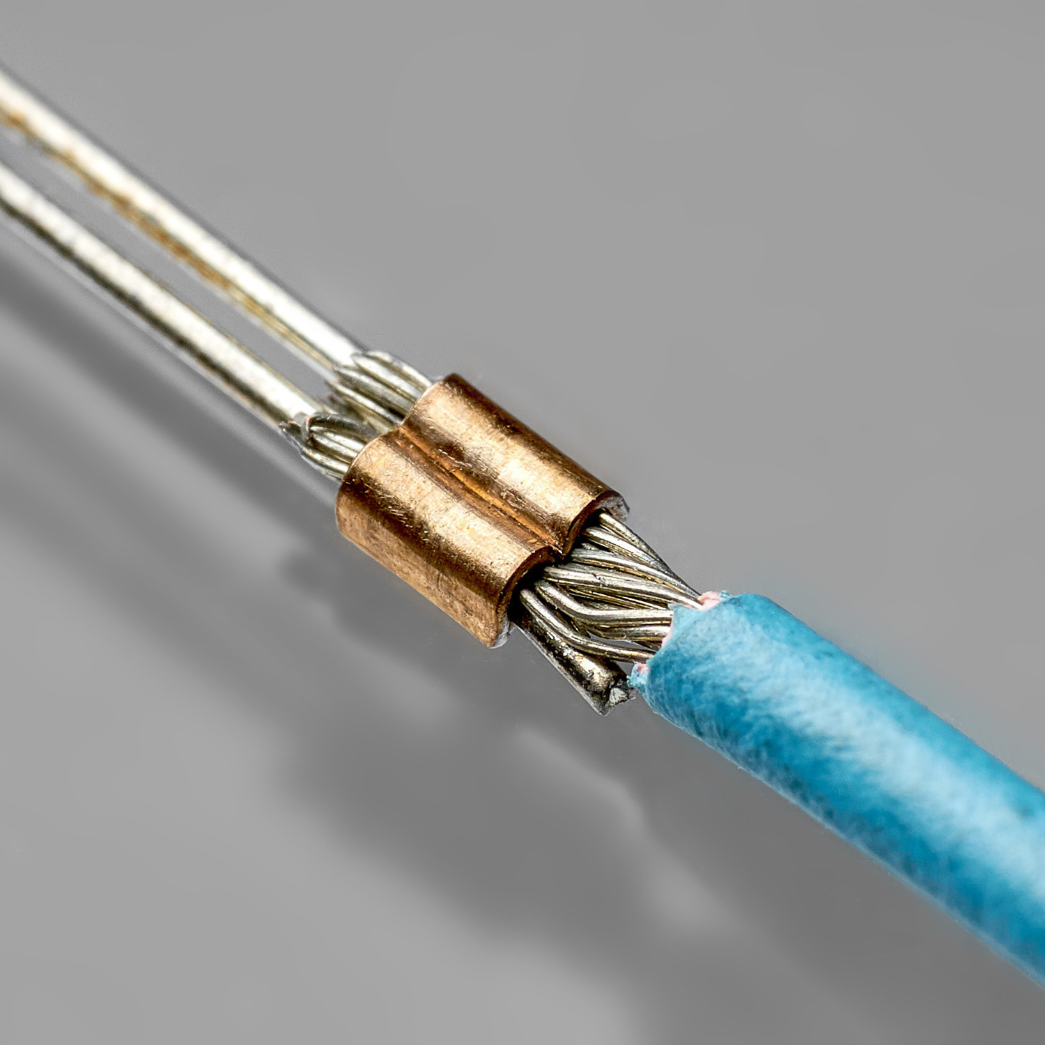
WIRE & WIRE
WIRE & METAL TAB
PCB & COAXIAL CONNECTOR
WIRE & METAL TAB
WIRE & PIN
WIRE & METAL TAB
WIRE & PLASTIC CONNECTOR
WIRE & METAL TAB
WIRE & PLUG ADAPTER
WIRE & METAL TAB
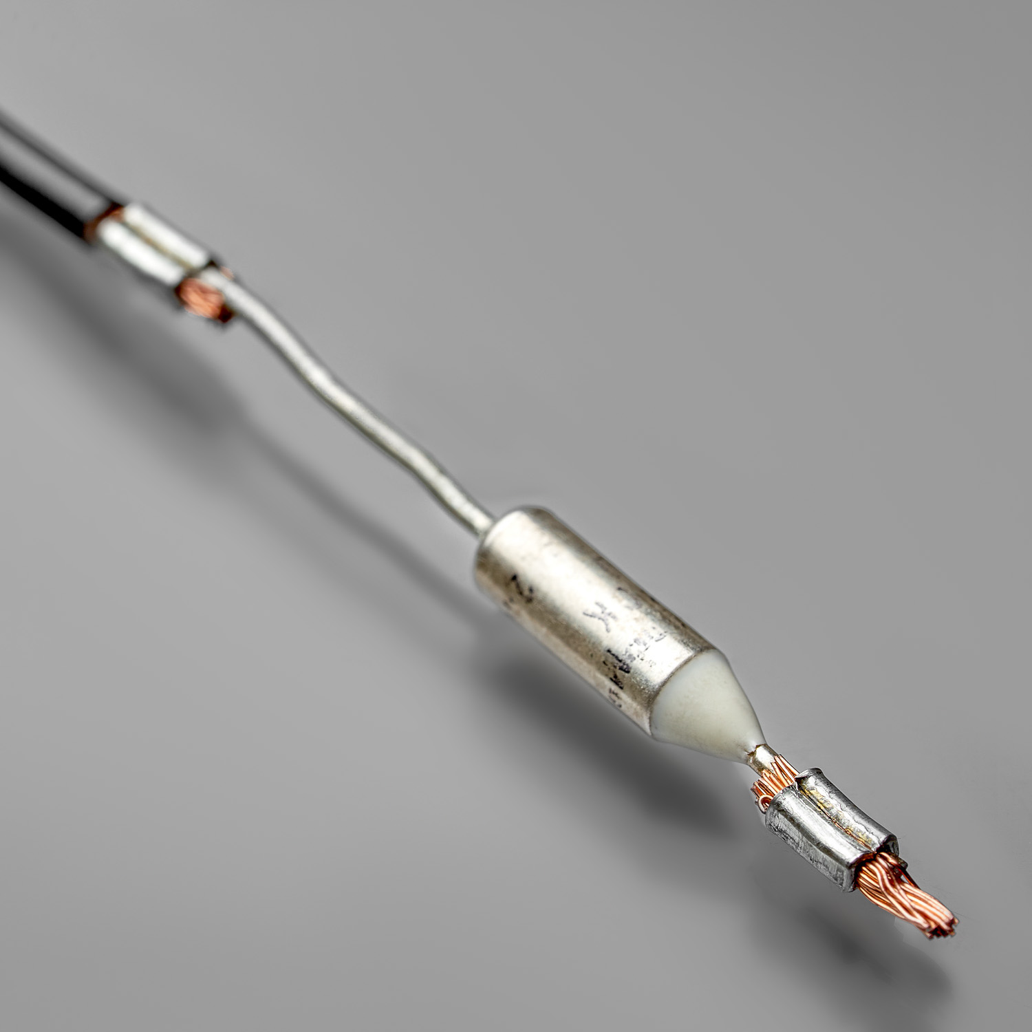
WIRE & THERMAL FUSE
WIRE & METAL TAB
ссылки на доп. картинки
0-1
0-2
0-3
0-4
0-5
0-6
1-1
1-2
2-1
3-1
3-2
4-1
4-2
4-3
4-4
4-5
5-1
6-1
7-1
7-2
7-3
7-4
7-5
8-1
8-2
9-1
9-2
9-3
9-4
9-5
9-6
10-1
10-2
10-3
10-4
10-5
10-6
10-7
10-8
10-9
10-10
10-11
10-12
11-1
11-2
11-3
11-4
11-5
11-6
11-7
11-8
11-9
11-10
11-11
11-12
12-1
12-2
12-3
13-1
13-2
13-3
13-4
13-5
13-6
13-7
13-8
13-9
14-1
14-2
14-3
14-4
14-5
14-6
15-1
16-1
16-2
16-3
16-4
16-5
OTHER EQUIPMENT


SCS (Splice Crimping Station)
Automatic manipulation of components in X-Y-Z and exchangeable jig concept
Read More
HSCS (High-Speed Splice Crimping Station)
Semi-automatic stripping of cables and fully automatic feeding of components in tape / reel / vibrating bowl format for splice crimping
Read More