
24 Mar
2025
2025
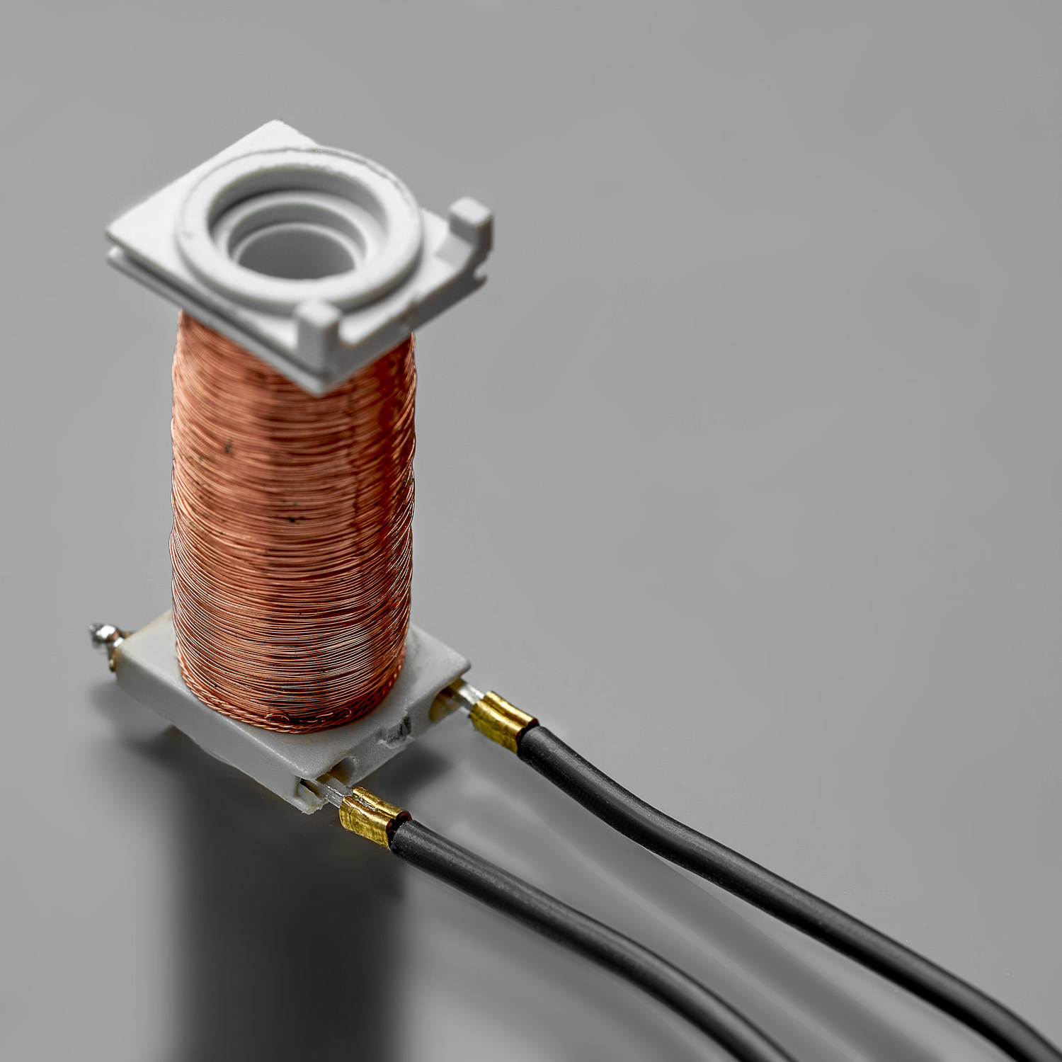
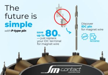
New patented IDC pin for magnet wire allows up to 80% cost savings
SM Contact developed the state-of-the-art solution for coil manufacturers. Just replace your IDC for magnet wire.
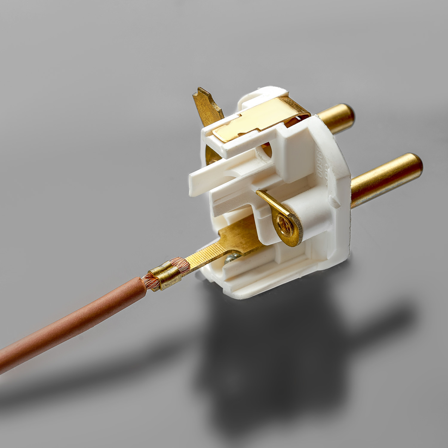
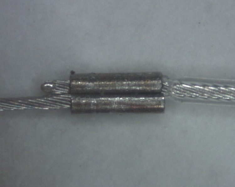
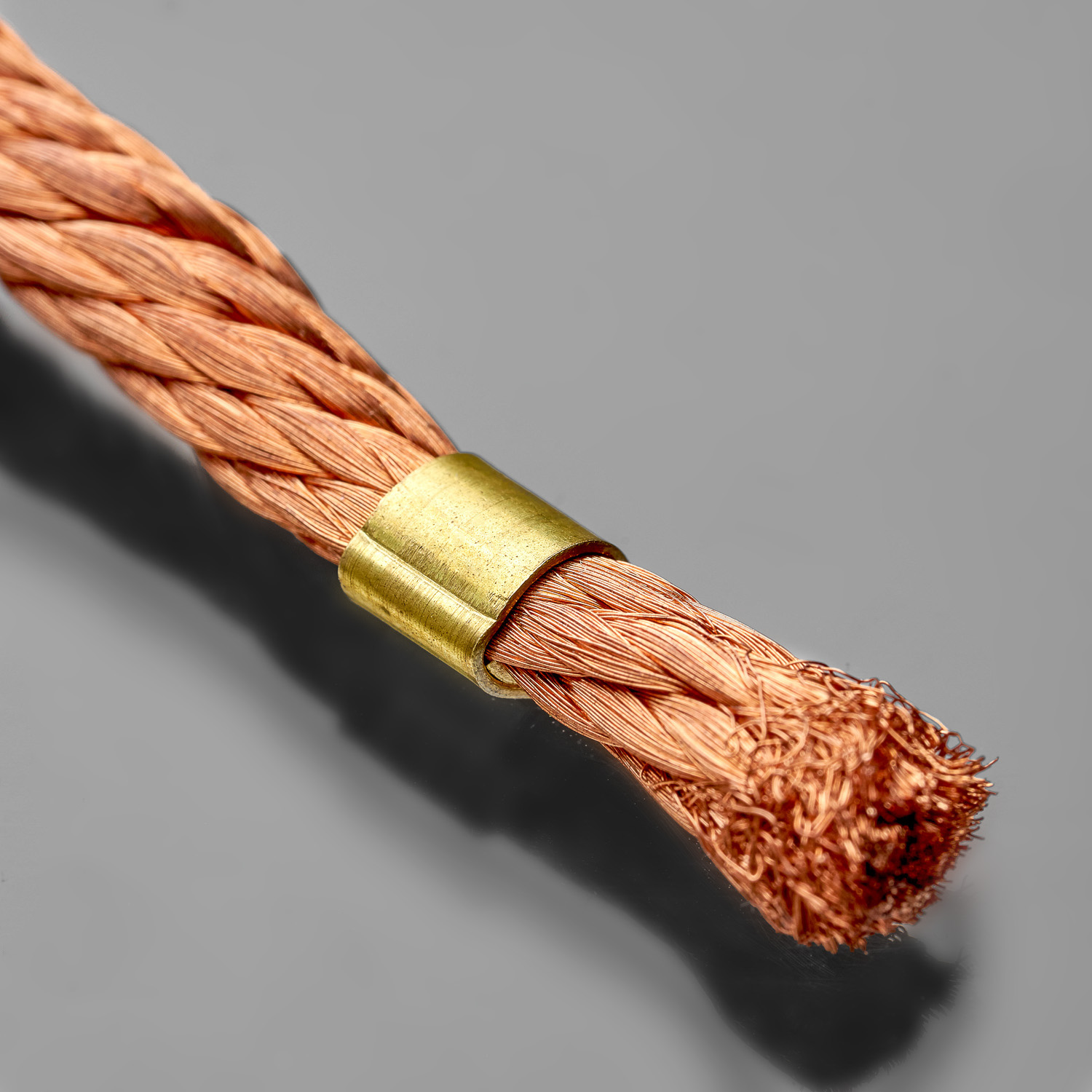
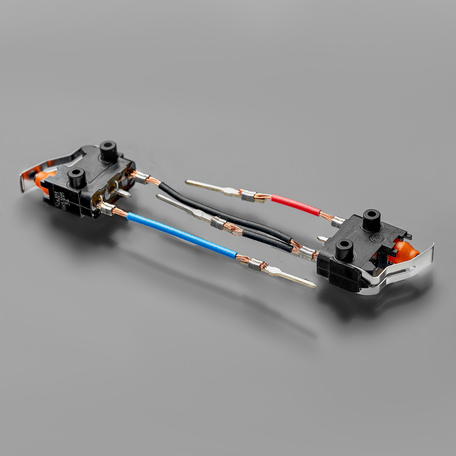
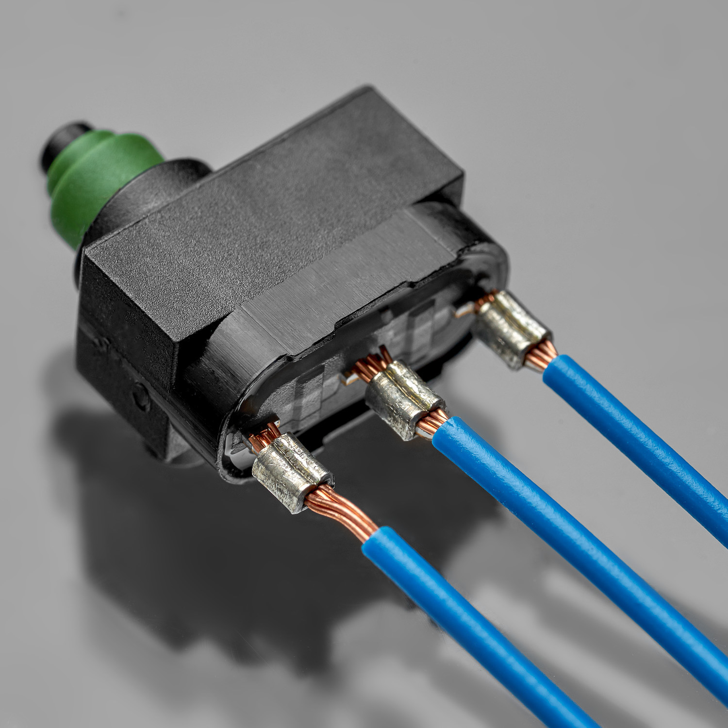
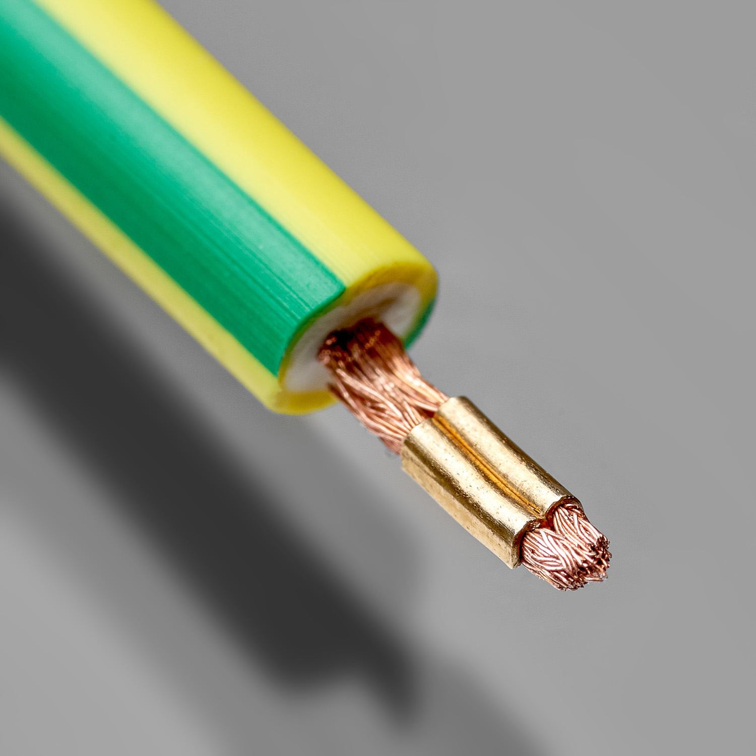
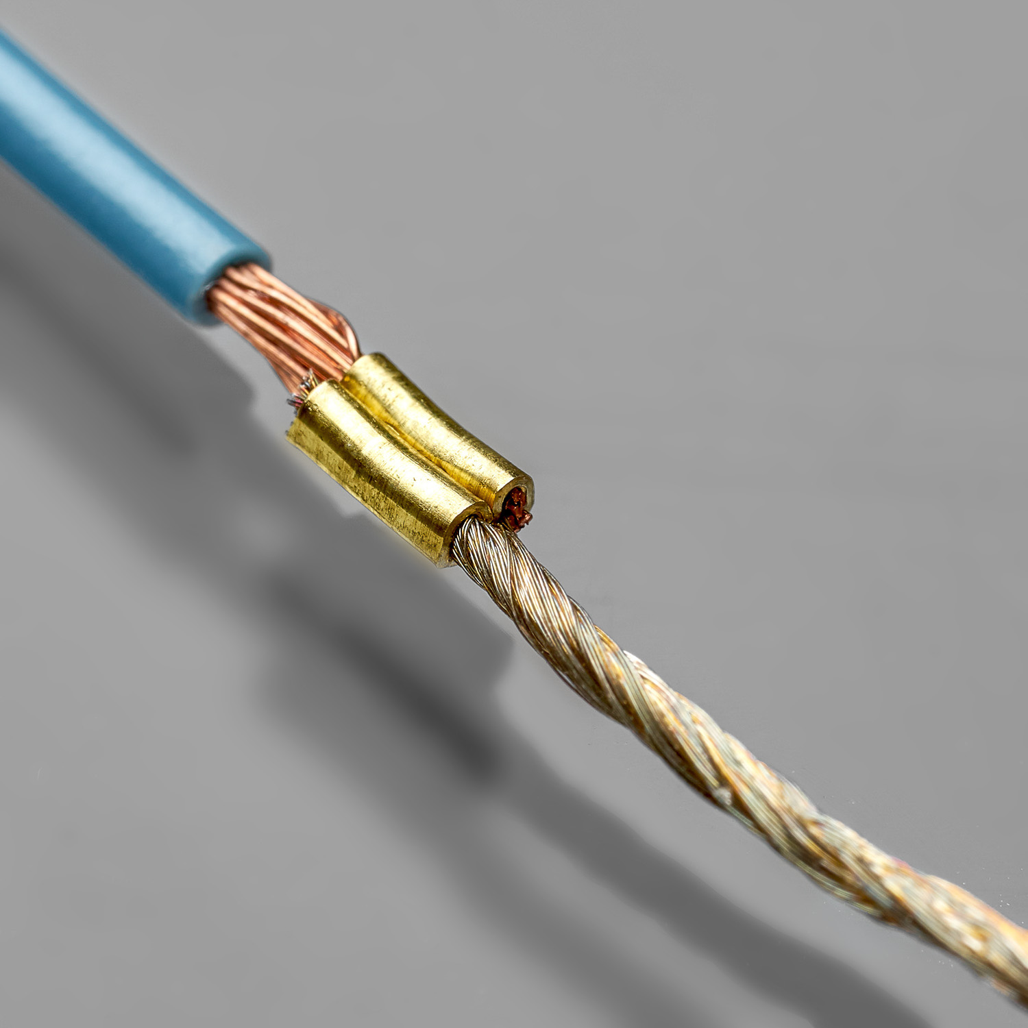
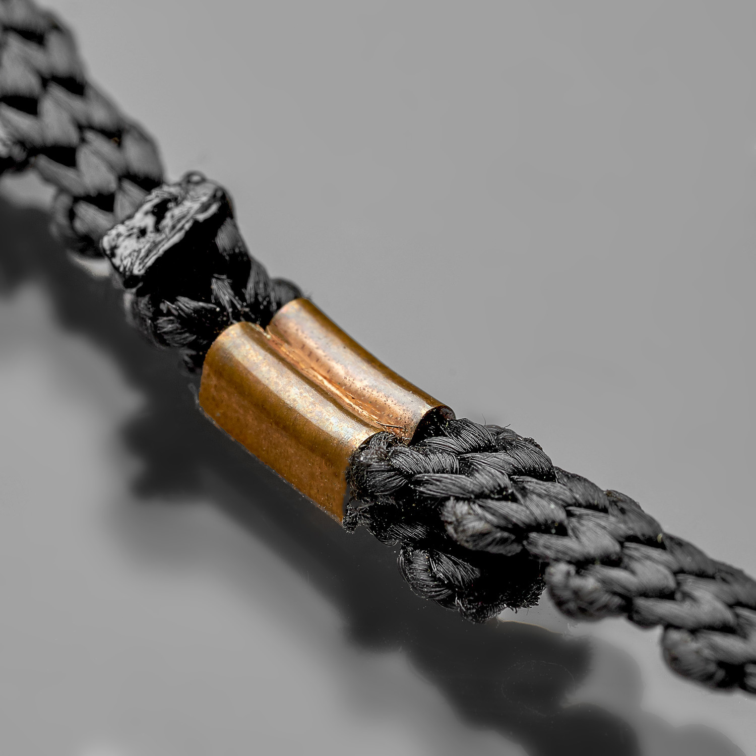
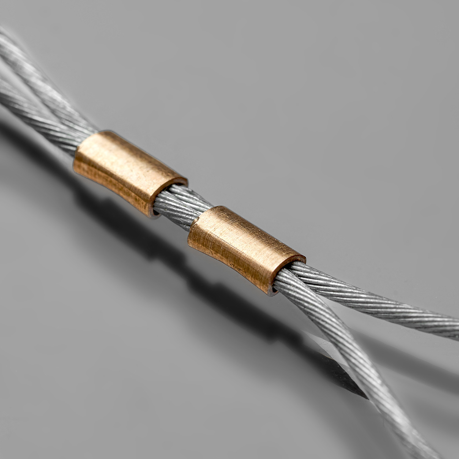
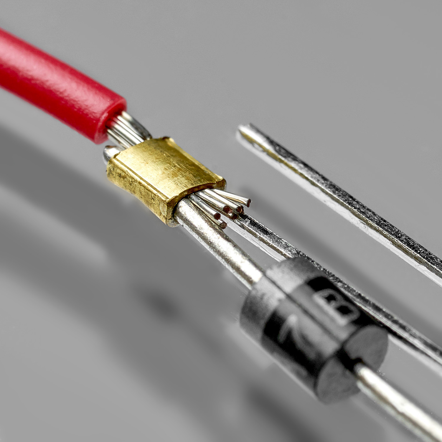
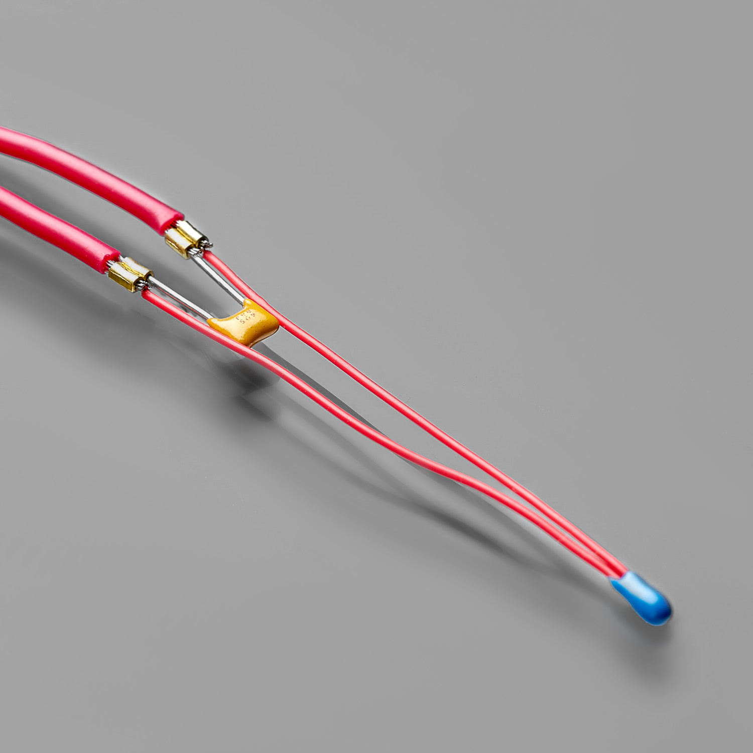
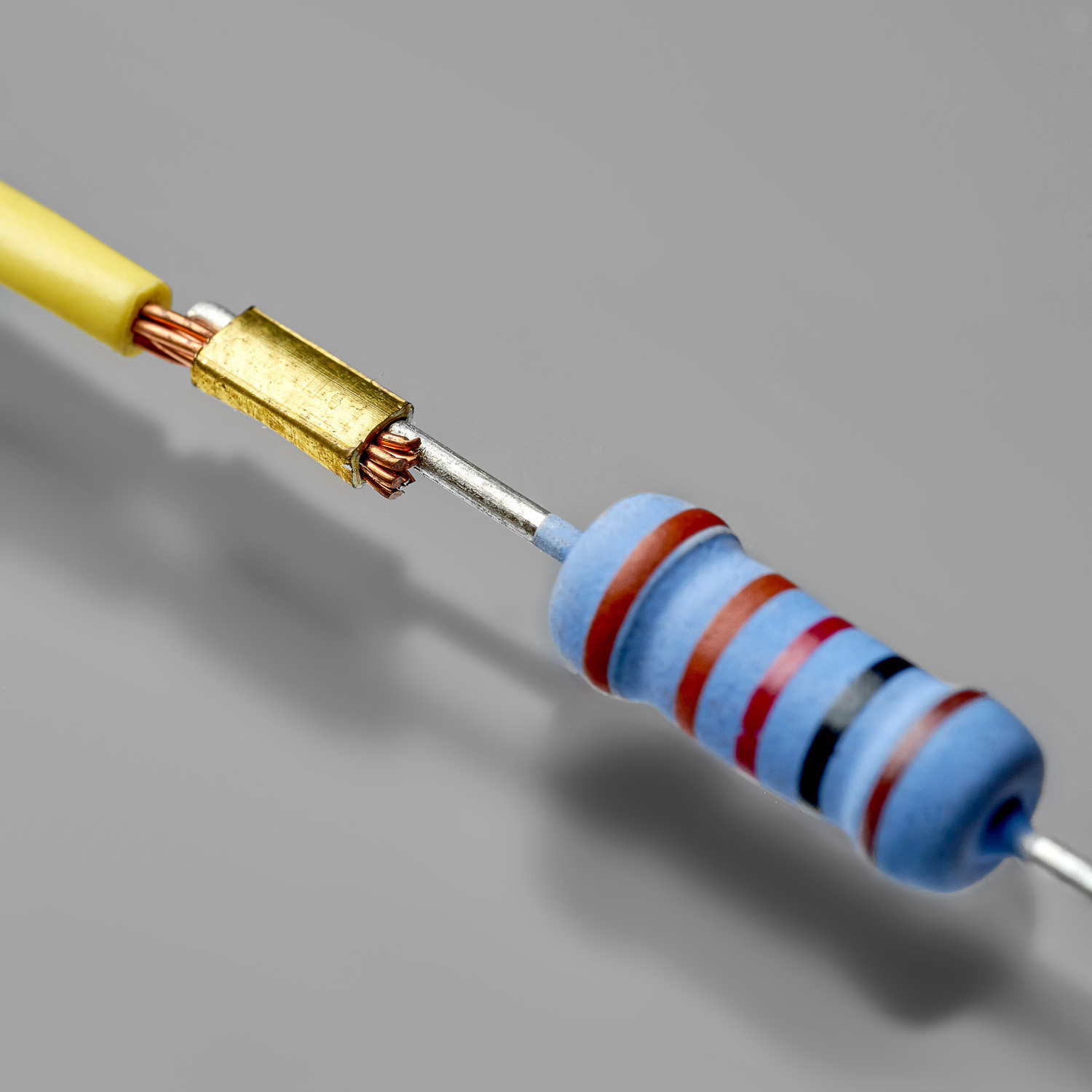
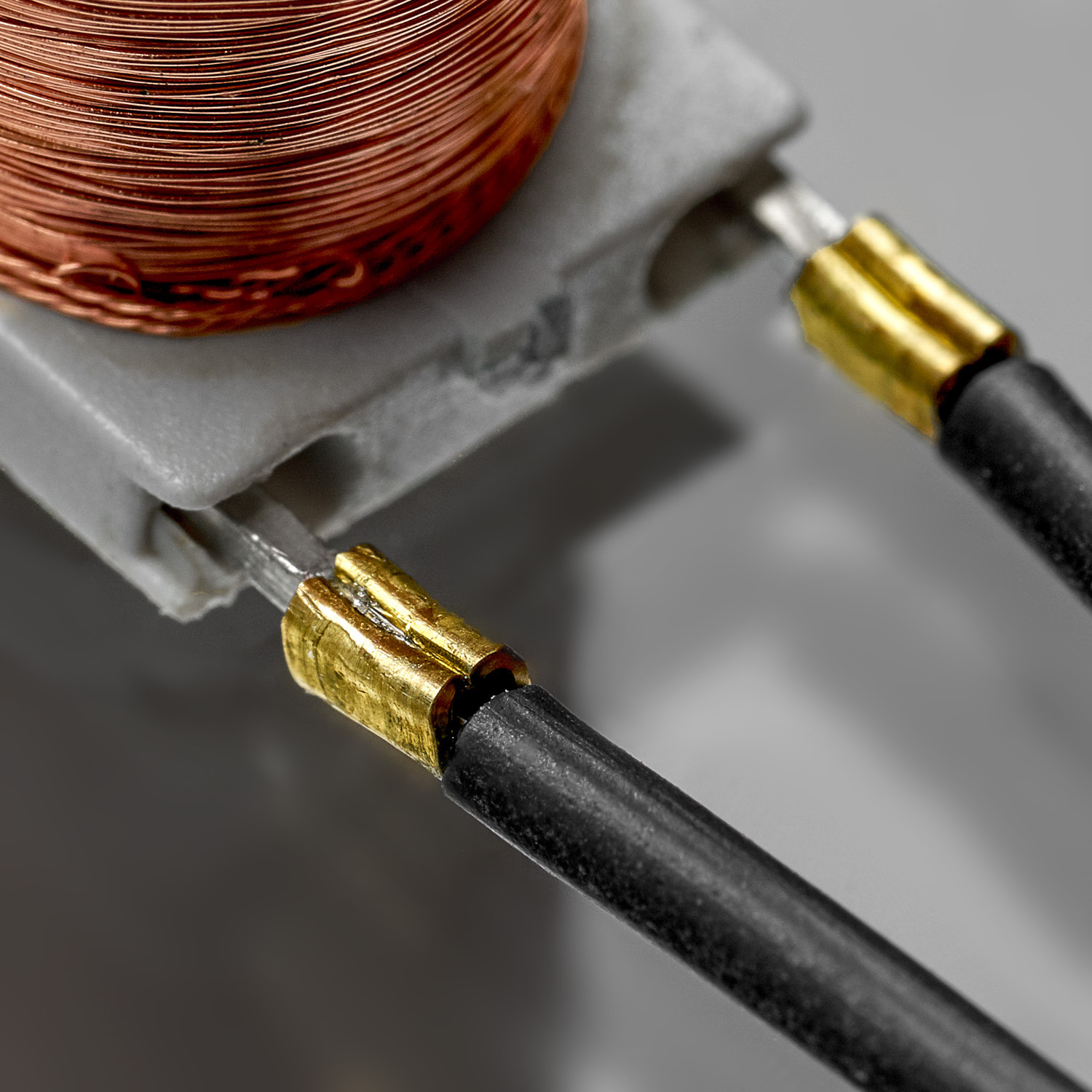
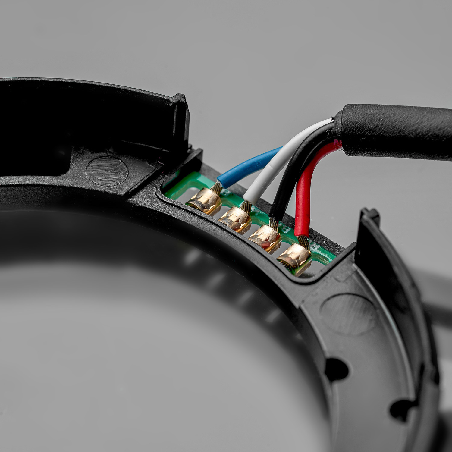
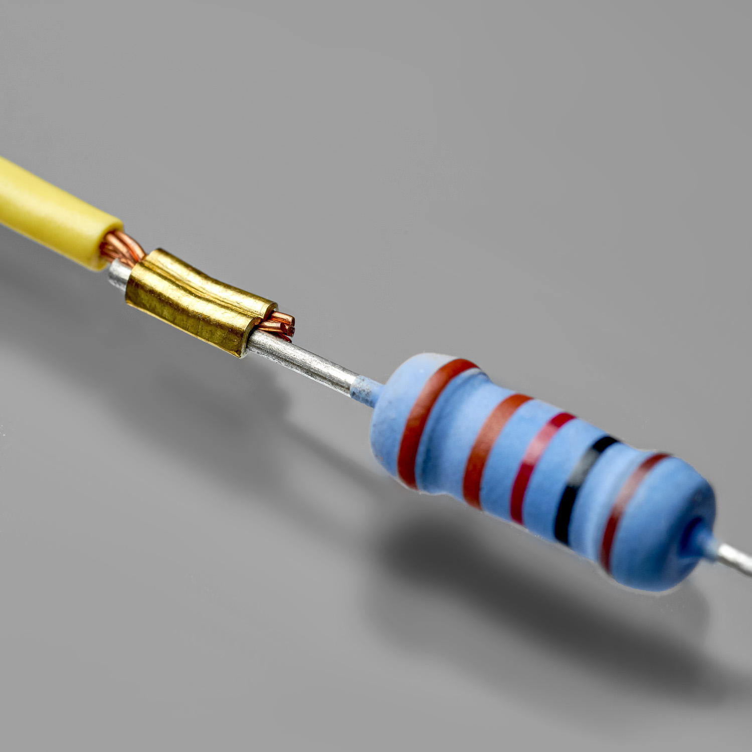
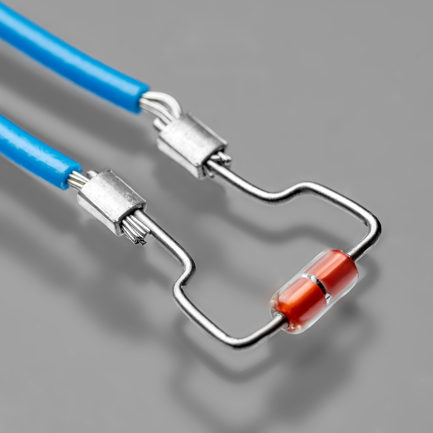
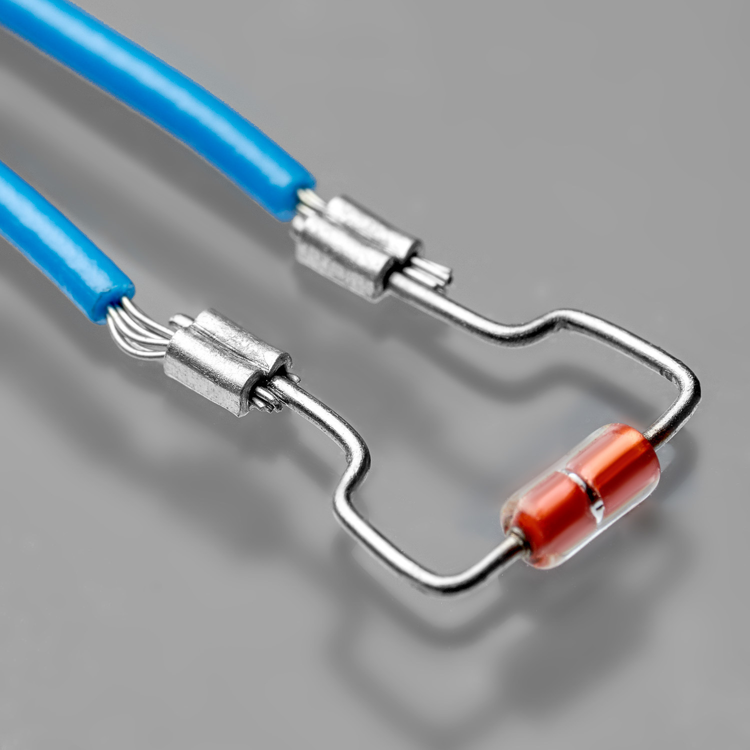
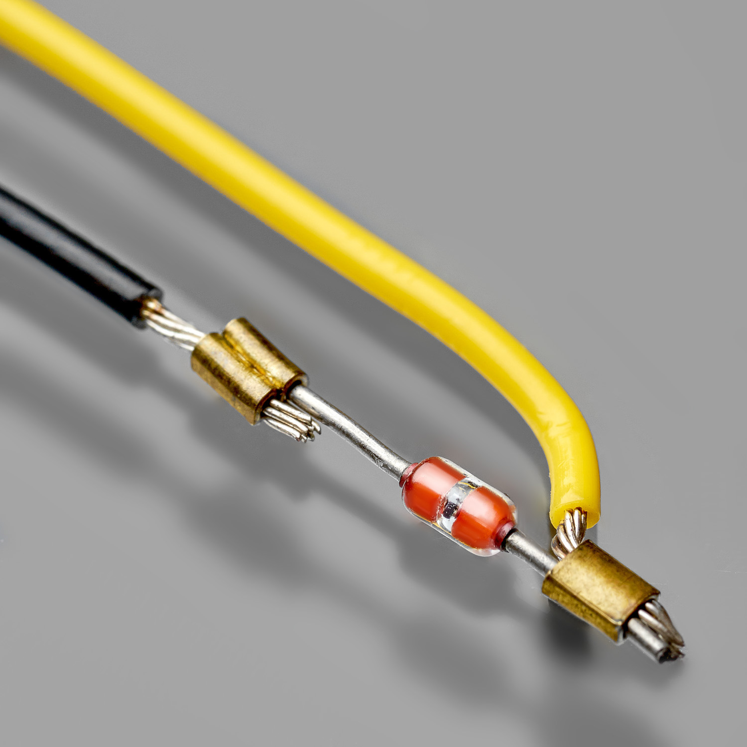
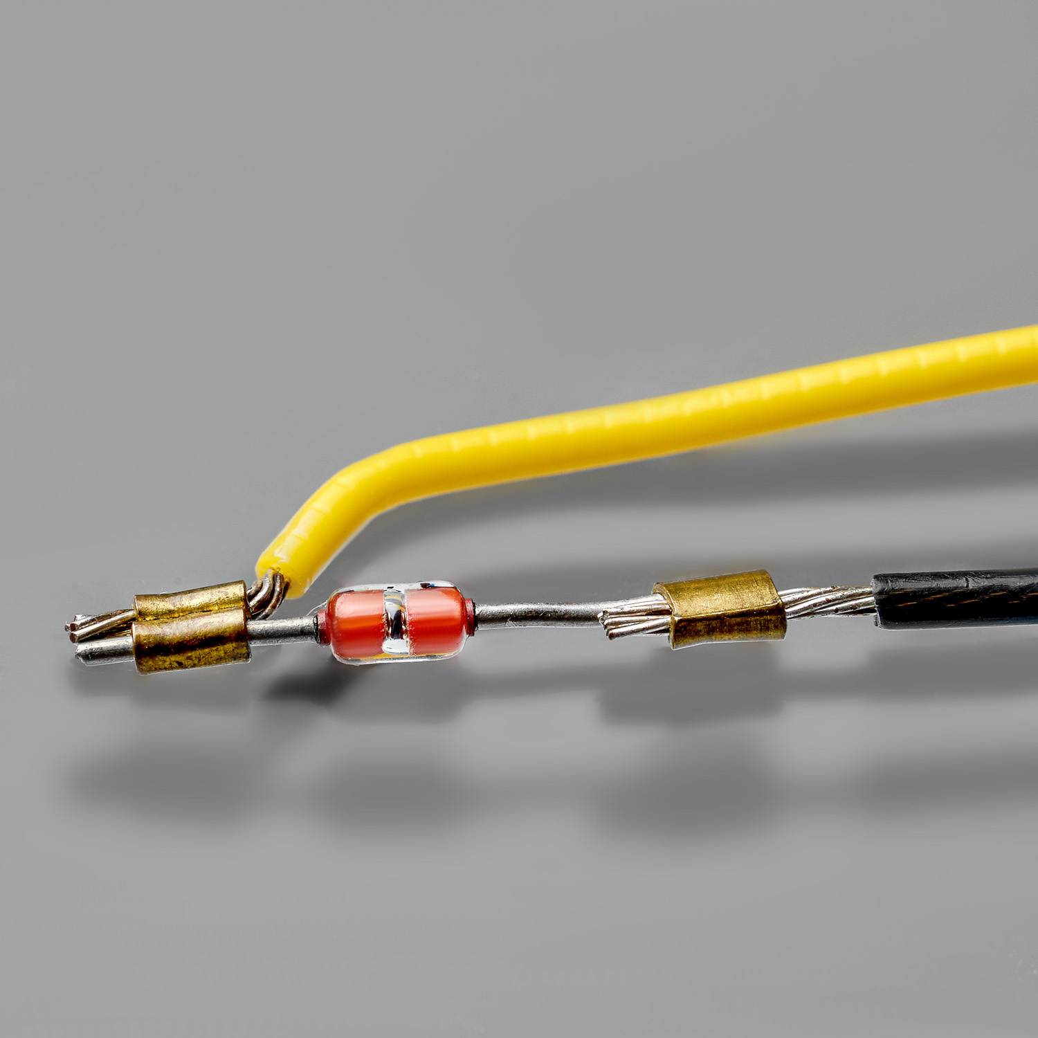
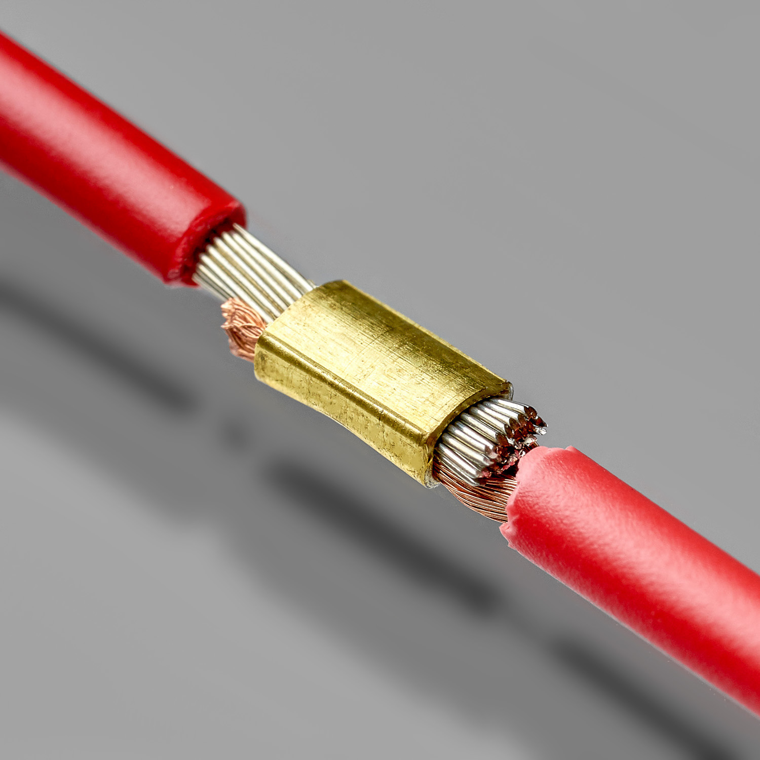
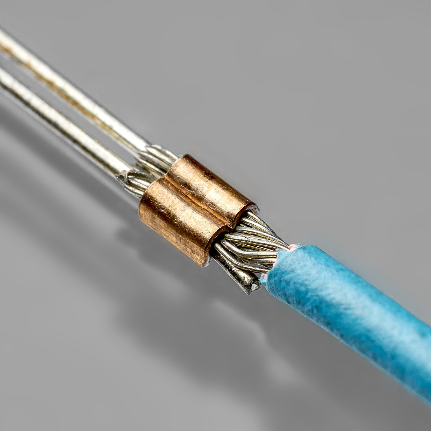
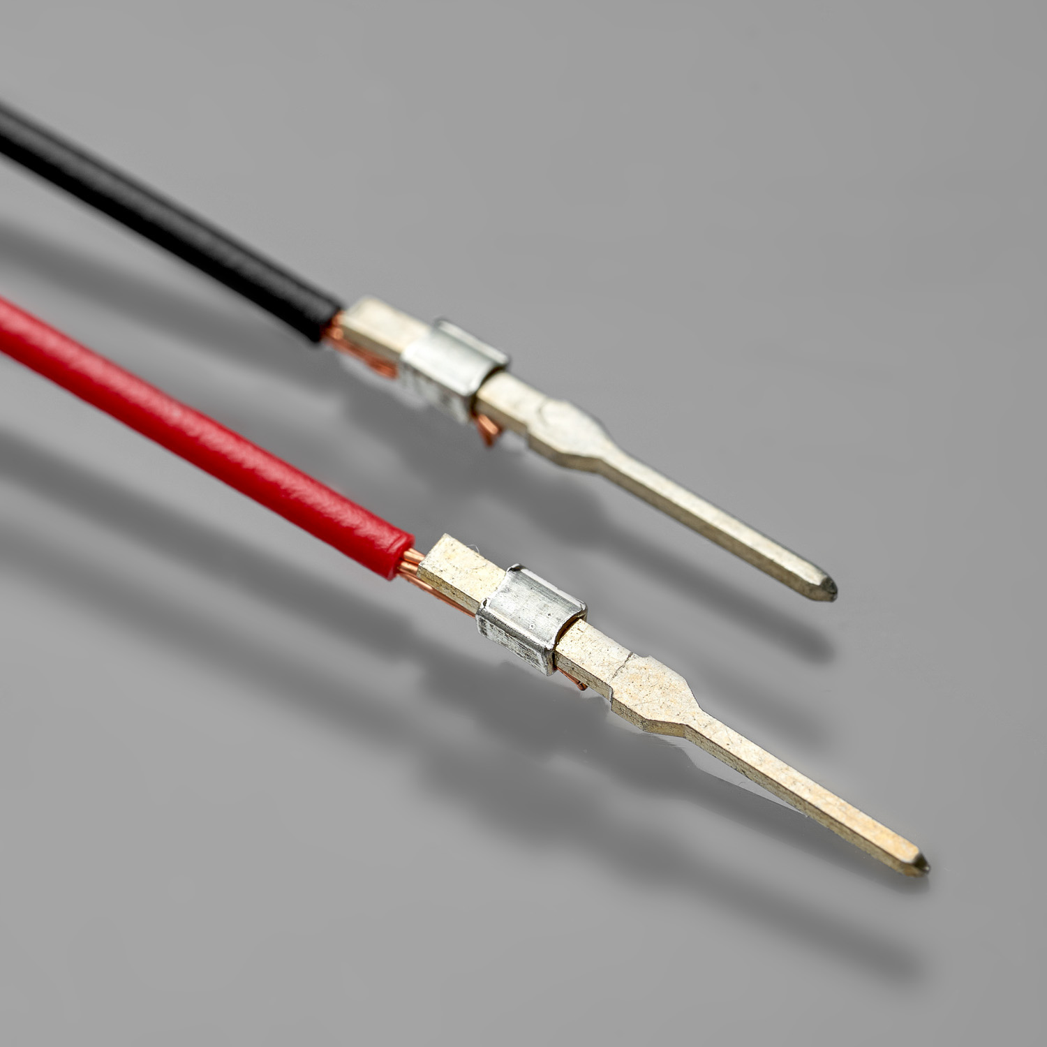
Read MoreSplice is a solderless crimp connection formed by crimping a metal clip onto the ends of the components.
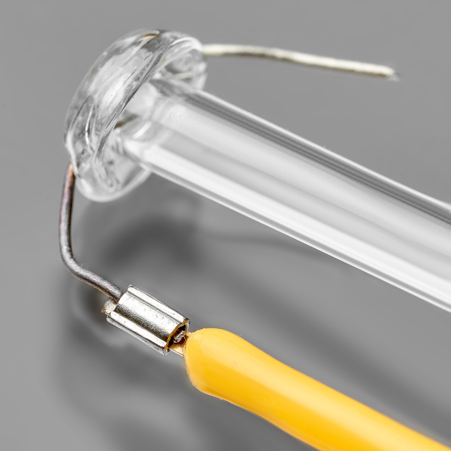
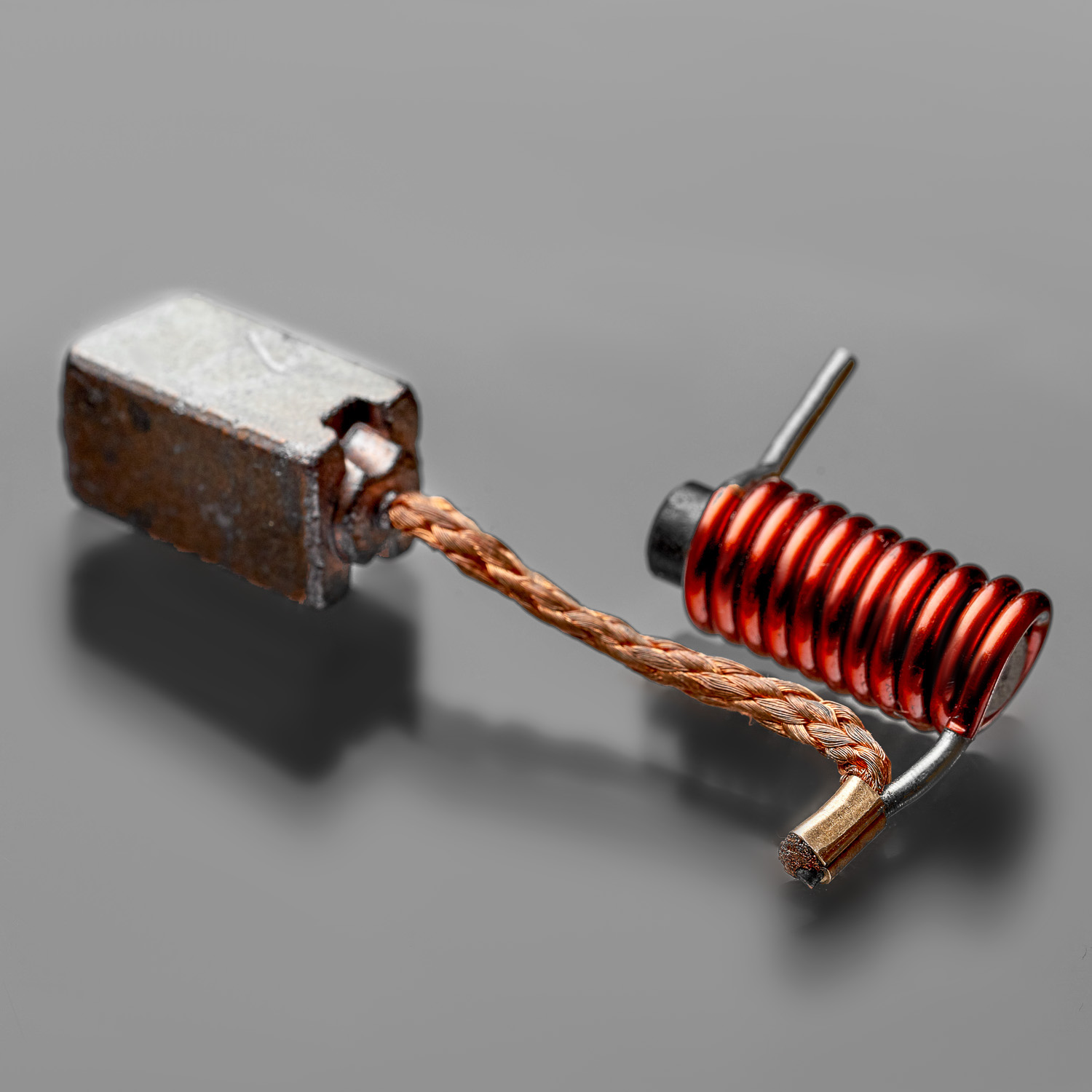
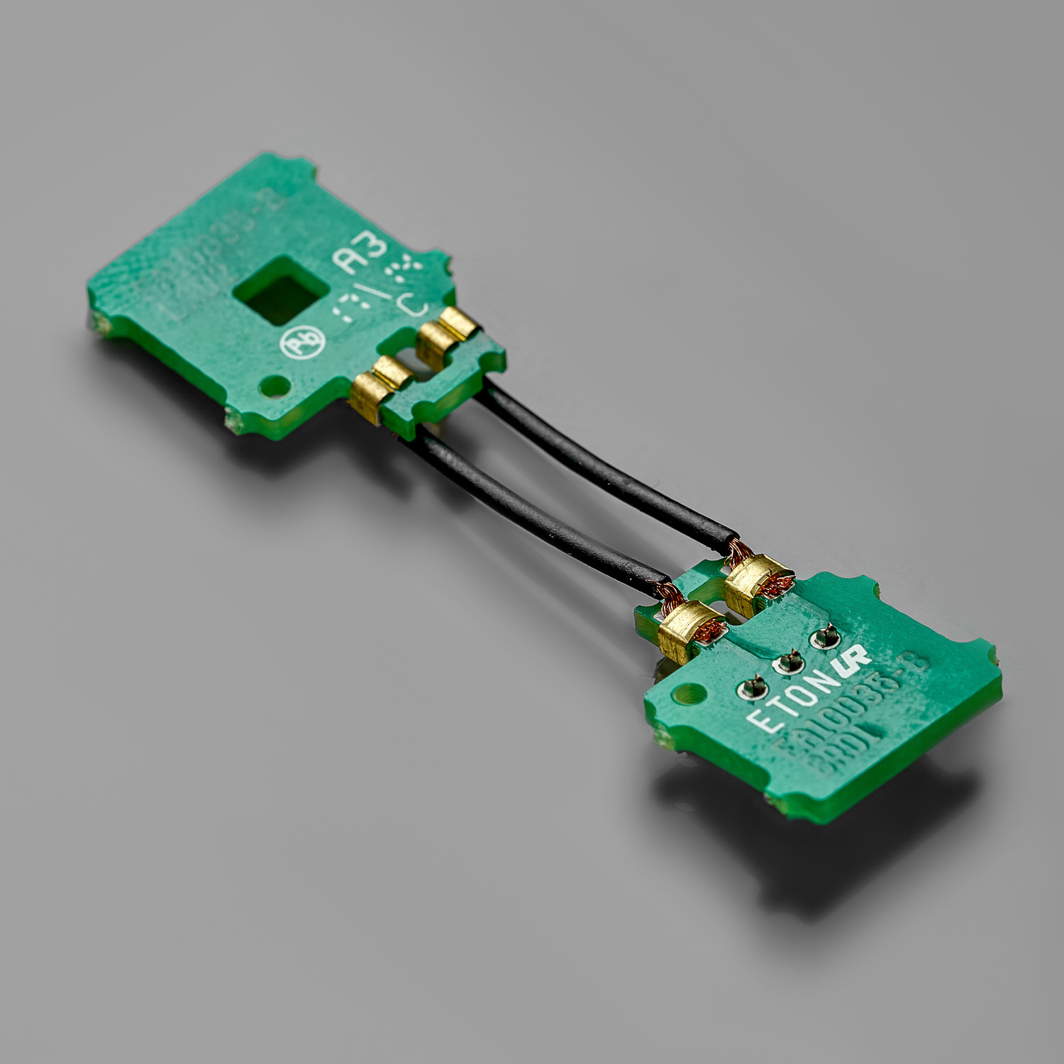
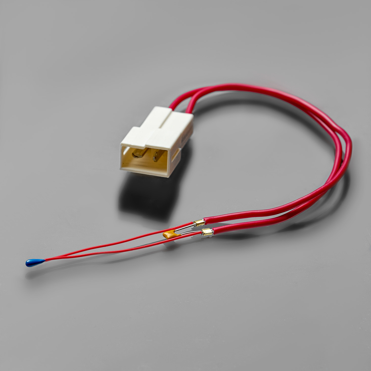
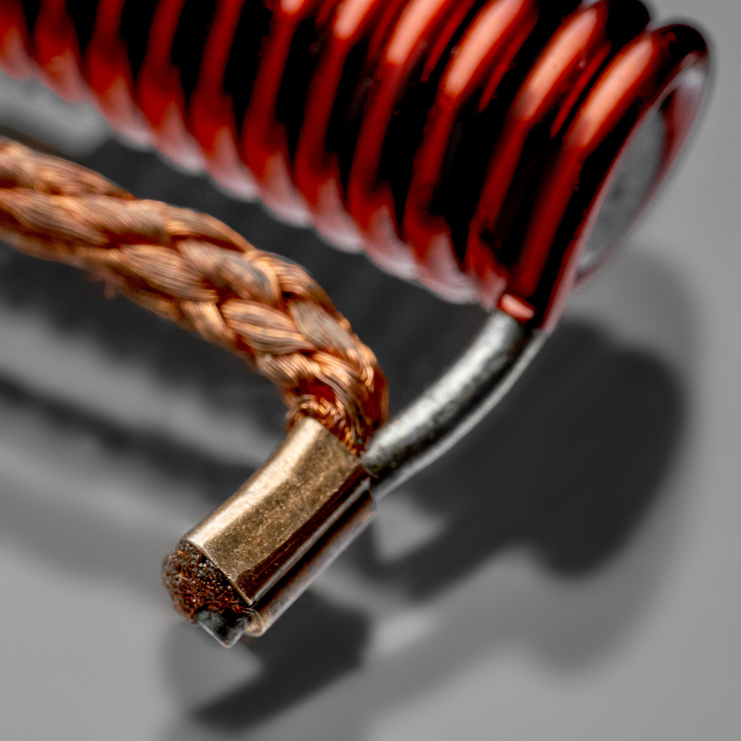
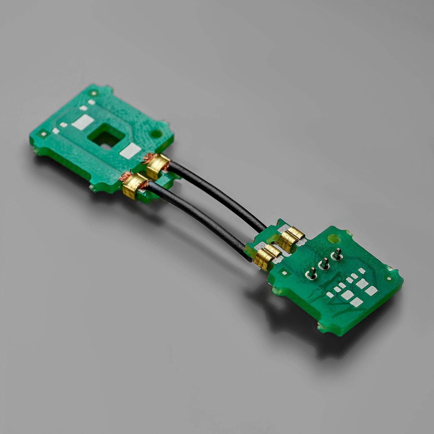
Unlike standard terminals, splice connection is applicable to any electrical components of various dimensions and materials: wire, PCB, coil, capacitor, sensor, diode, lead frame, textile, etc. In contrast to welding and soldering, it is vibration resistant and its quality can be evaluated both within and after production.
Customization and reliability of splice solution is further enhanced, since our R&D department defines optimal connection, tooling and splice band parameters in the beginning of the project.
Splice connections are widely used by automotive components suppliers of VW, BMW, PSA, Renault, etc.
Find out more about splice advantages and application below.


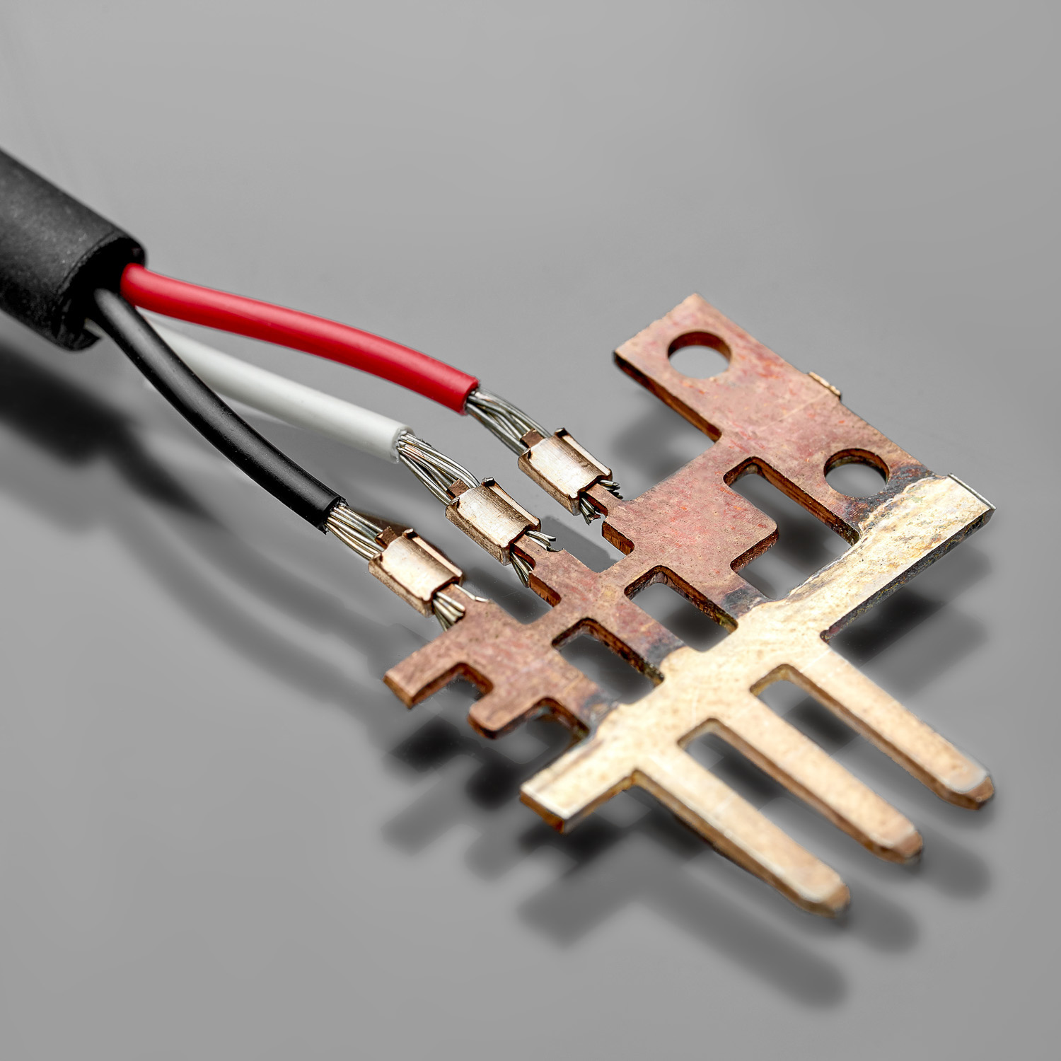
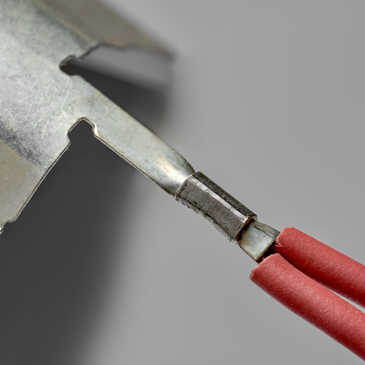
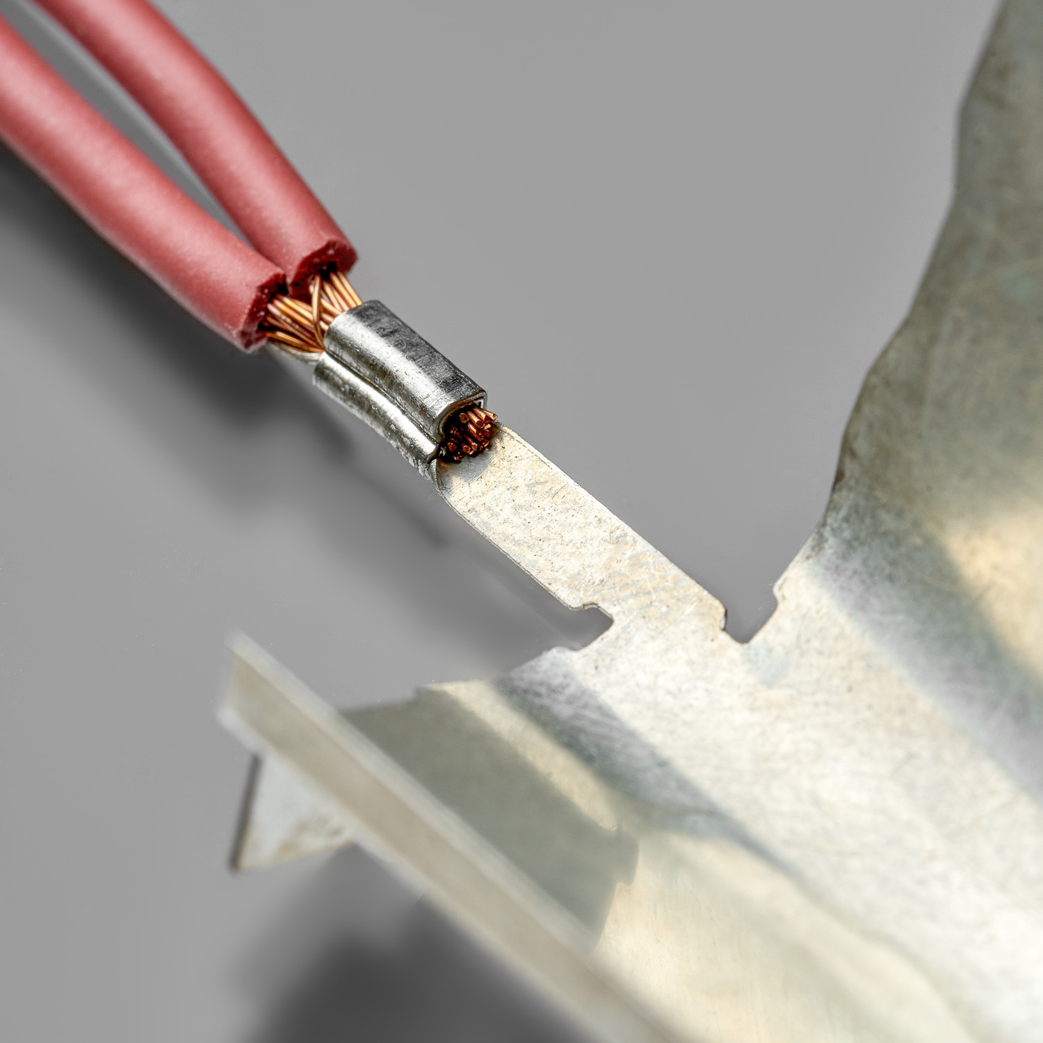
WIRE & METAL TAB
WIRE & METAL TAB
WIRE & METAL TAB
WIRE & METAL TAB
WIRE & METAL TAB
WIRE & METAL TAB
WIRE & METAL TAB
WIRE & METAL TAB
WIRE & METAL TAB
ссылки на доп. картинки
0-1
0-2
0-3
0-4
0-5
0-6
1-1
1-2
2-1
3-1
3-2
4-1
4-2
4-3
4-4
4-5
5-1
6-1
7-1
7-2
7-3
7-4
7-5
8-1
8-2
9-1
9-2
9-3
9-4
9-5
9-6
10-1
10-2
10-3
10-4
10-5
10-6
10-7
10-8
10-9
10-10
10-11
10-12
11-1
11-2
11-3
11-4
11-5
11-6
11-7
11-8
11-9
11-10
11-11
11-12
12-1
12-2
12-3
13-1
13-2
13-3
13-4
13-5
13-6
13-7
13-8
13-9
14-1
14-2
14-3
14-4
14-5
14-6
15-1
16-1
16-2
16-3
16-4
16-5
Reproducible quality
Splicing as a mechanical process allows getting reproducible high quality. With the same tooling and splice band the quality of a product stays the same from cycle to cycle.


Adaptable to product
Tooling is designed individually for each product so that the splice fits perfectly the components and form reliable connection.
Gastight
The deformation of the components and the splice during the splicing process guarantees gastight connection.


Low electrical resistance
Connection and tooling engineering guarantees stable low electrical resistance preventing loose strands, misaligned connection and other defects.
Deformation and vibrations resistance
Splice crimping doesn’t involve heating unlike soldering, thus it keeps components out of burning or melting risks and guarantees good behavior under deformation and vibrations.


Compact
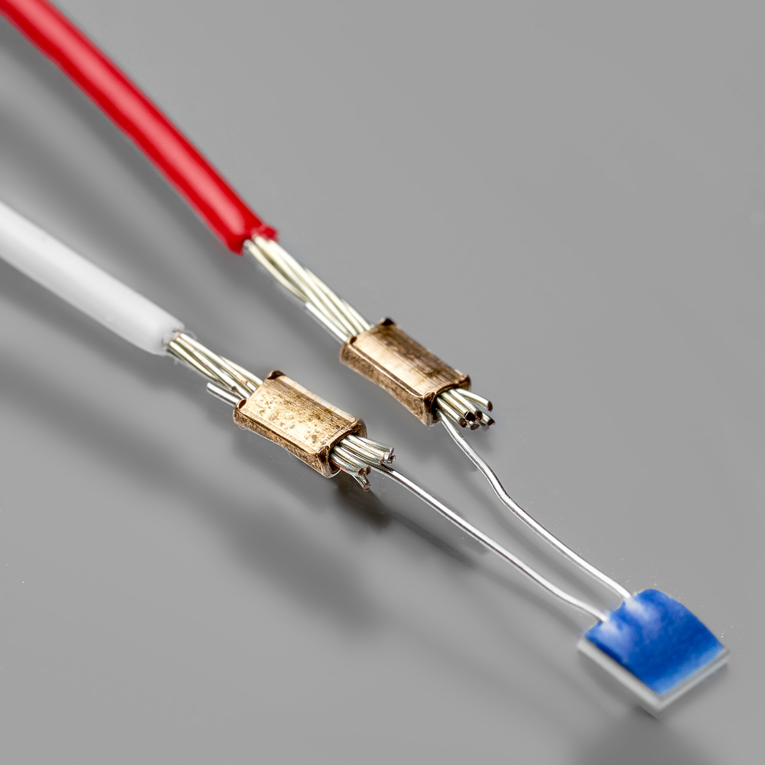
Splice allows to make compact and constant size connection with minimum dimensions such as 0.46*0.24 mm cross-section connection for an artificial cardiac pacemaker. Space saving feature is ideal for sensors, bulbs, heating elements, etc.
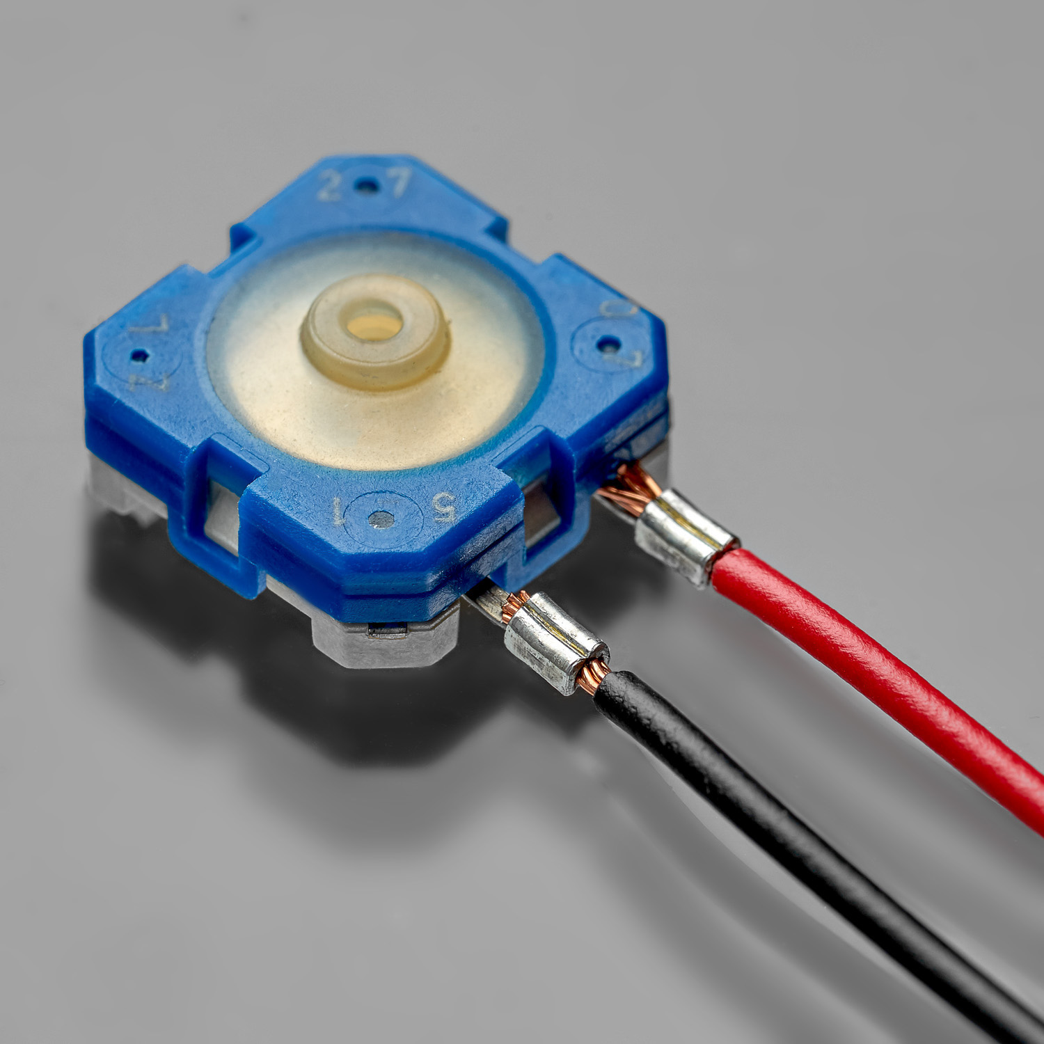
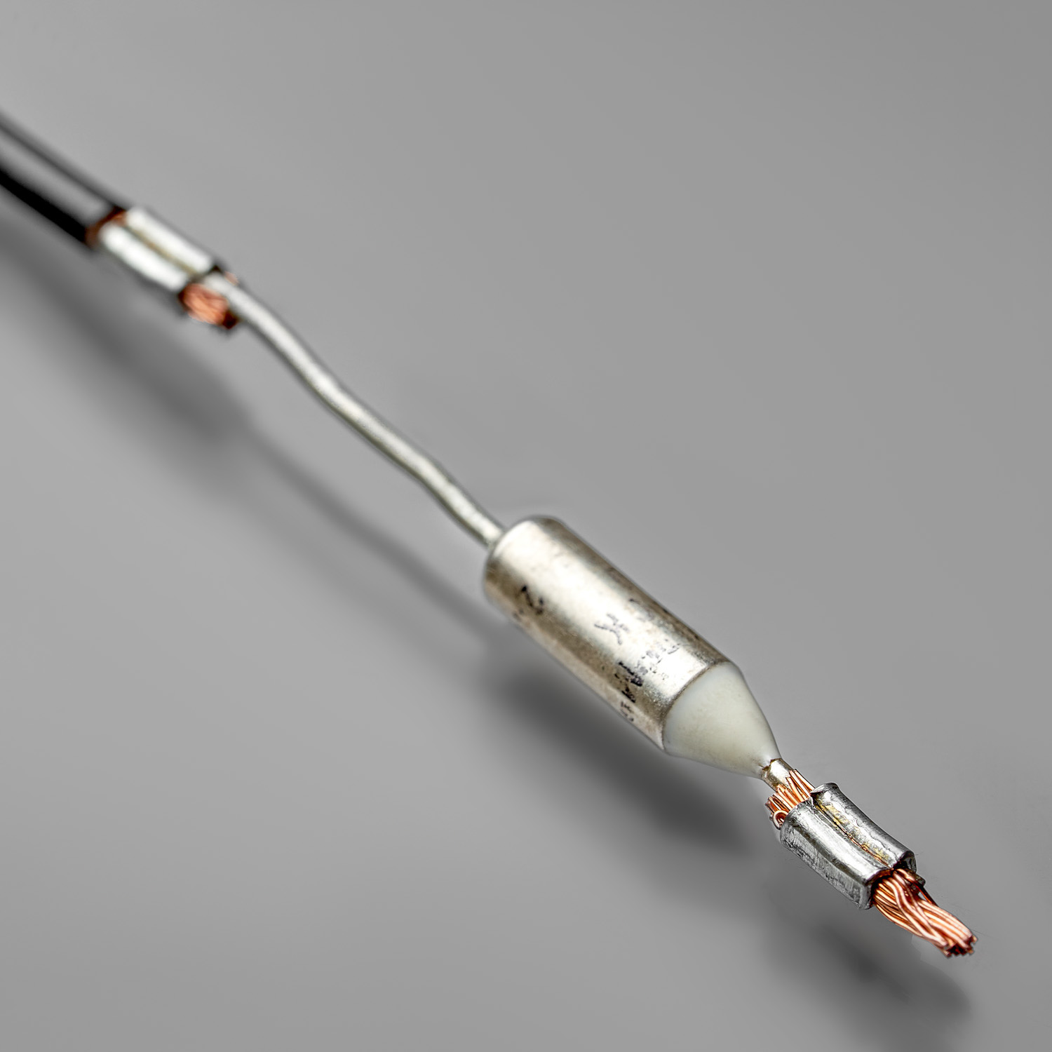
Universal
Splice connection can be performed with various types of components (PCBs, wires, coils, sensors, plastic connectors, filament, etc.), materials (fiber, Teflon, chrome, steel, etc.) and size.


Quality control
Splice quality is easy to be controlled unlike soldering with a help of inline systems (Crimp Force Monitor, camera position and color control, Poka Yoke, etc.) or standalone laboratory equipment (cross section, pull force, crimp height measurement, etc.).
Easy to go
Thanks to automation it’s possible to make up to 2000 splices per hour without any experience in splicing.


Cost-efficient
Splice spare parts are cheaper than ones for welding and soldering and it need to be changed rarely: each 300 000 – 3 000 000 assemblies depending on spares and components type.
1. SPLICE BAND DEFINITION
We define splice band features depending on type of application, component materials, working environment and temperature range.
What you get?
Splice band material (LA, LE, CN, CE, IN), type (standard serrated, M-type), thickness (0.2 – 0.53 mm), length (1.5, 2, 3, 4, 6, 7 mm), and height.
2. TOOLING DEFINITION
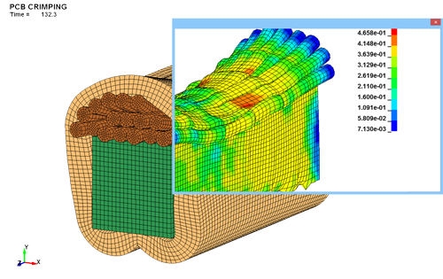
With a help of FEA software and database of former realized connections, we build computer model of tooling and simulate strains and stresses during splice crimping.
What you get?
Equipment type, clincher type (standard, CI-type or special) and size, punch tip shape (standard or double trumpet), special tool necessity definition.
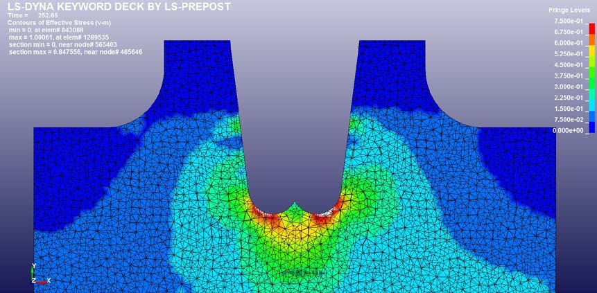
3. SPLICE CONNECTION SIMULATION
With a help of FEA software we build components computer model of defined type and materials and simulate strains and stresses during splice crimping.
What you get?
Optimal connection parameters and its improvement options are specified to match industry norms and Customer’s demand (connection dimensions and optimal components positioning, compression rate, internal stress levels, contact resistance, and interconnection surface).
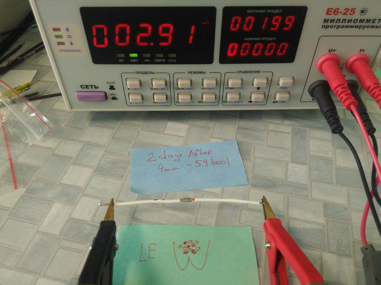
4. LABORATORY TESTS
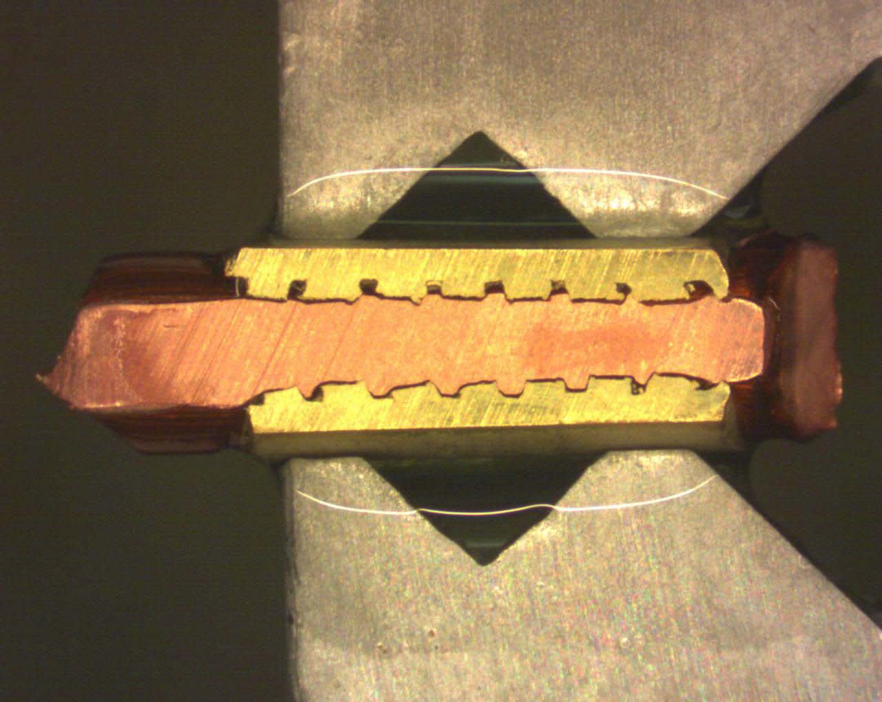
We make samples and perform laboratory study: pull-force, electrical resistance, and galvanic corrosion measurements, as well as thermal stress test and cross-view research.
What you get?
Report and datasheet with precise connection parameters matching splice/crimp norms and validated for different splice heights and compression levels according components tolerance (optimal connection cross-view shape, tooling requirements, target connection dimensions for machine adjustment, etc.).
5. EQUIPMENT MANUFACTURING
Engineering department adapts automation level, speed, special options and quality control devices.
What you get?
Splice crimping equipment customized for Customer’s application, as well as for quality, automation, cost and production volume requirements.
6. FPC SOLUTION
– Control List with all optimal connection dimensions and tolerances.
– Viso 6microsection measurement software.
– Annual re-validation of a connection.
What you get?
Automated splice quality control and timely support from SM Contact engineering staff.
Check out splice equipment options! Each machine can be customized to particular components, environment, automation level, and production volumes.

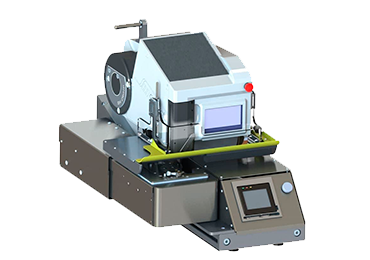
SM Crimp V8
Splice crimping
with manual
components
positioning
Read More
SM Crimp V8 Advanced
Splice crimping
with
semi-automatic
positioning
Read More

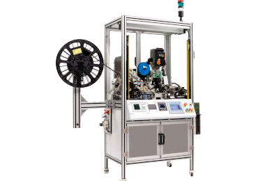
ACS (Automatic Crimping Station)
Automatic manipulation
of components in X-Y-Z
and exchangeable
jig concept
Read More
SM Contact developed the state-of-the-art solution for coil manufacturers. Just replace your IDC for magnet wire.
Read More
SM Contact will present a new solution for magnet wire connections.
Read More
If we lived on Jupiter, one day would last less than 10 hours. We wouldn’t have time for anything. If we lived on Venus, we could do all things in one day.
Read More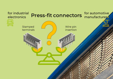
Check out advantages of continuous wire pin connector technology.
Read More
Keep the essential values in a changing world.
Read More
A few arguments in favor of splices in magnet wire applications.
Read More