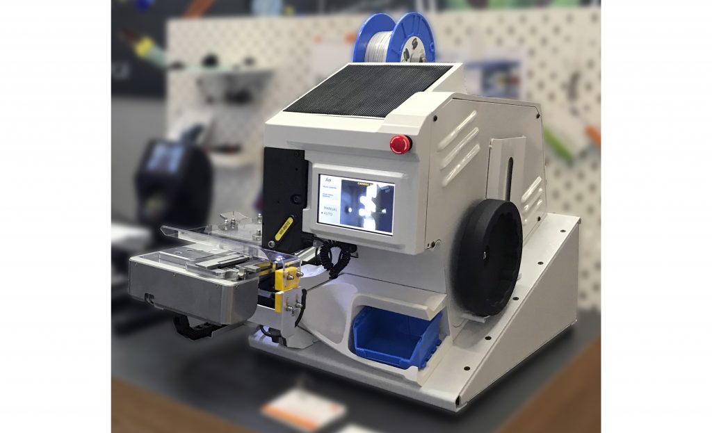
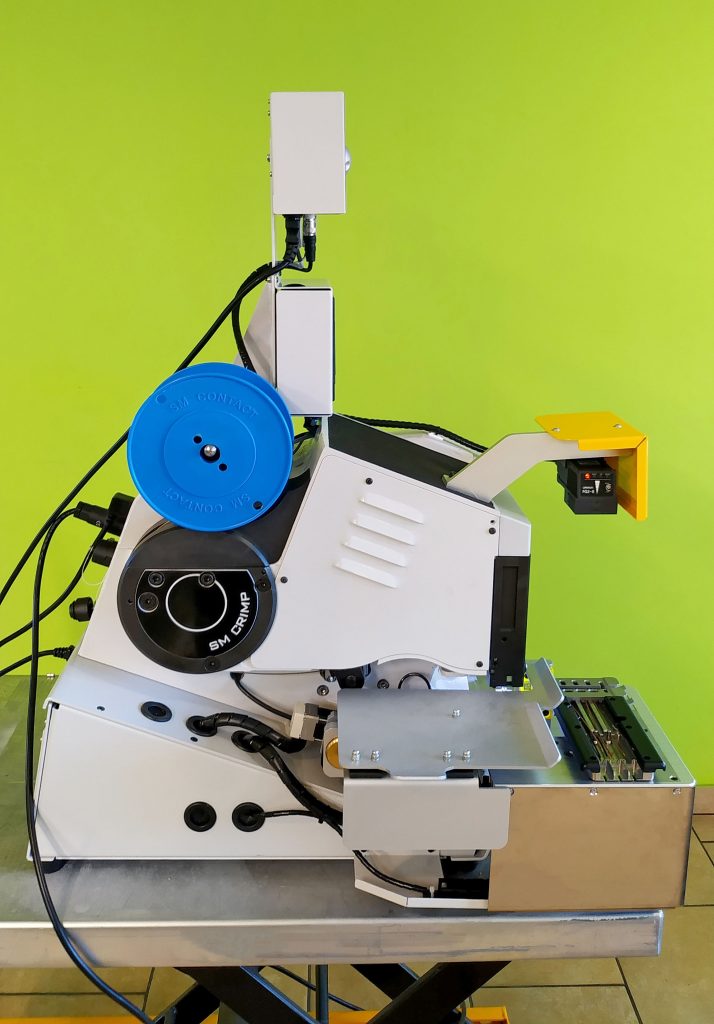
ÉQUIPEMENT STANDARD
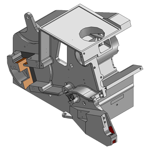
Cadre en fonte
À la différence des machines composées des parties séparées liées par les vis le cadre en fonte monobloc de la machine SM Crimp 2000 vous garantit le fonctionnement stable pendant le sertissage.
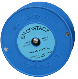
Ruban de sertissage
Le ruban de sertissage est sélectionné compte tenu du type du produit, du milieu de travail et de la gamme de température: type et matière du ruban (laiton, laiton avec revêtement d’étain, chrome-nickel, chrome-nickel avec revêtement d’étain, acier inoxydable), épaisseur (0,2–0,53 mm), longueur (1.5, 2, 3, 4, 6, 7 mm) et hauteur.

Contrôle de la hauteur de sertissage
Le panneau de contrôle de la hauteur de sertissage est muni de l’indicateur numérique et alphabétique pour, si nécessaire, régler la hauteur de sertissage nécessaire.

Système motorisé d’amenée du ruban
Le capteur spécial effectue le contrôle de la longueur de chaque morceau du ruban de sertissage coupé, et la surface en caoutchouc de la bobine exclue sa détérioration.
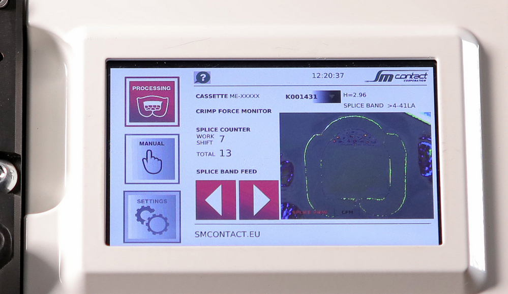
Platine de contrôle
Tous les éléments de commande, sauf l’interrupteur d’alimentation, sont disposés sur le panneau de contrôle. 5 boutons et 1 écran permettent de contrôler le nombre d’articles, les données d’entrée et de sortie, la langue de l’interface, les paramètres des outils, le système d’amenée et l’arrêt d’urgence.
L’interface est accessible en plusieurs langues.
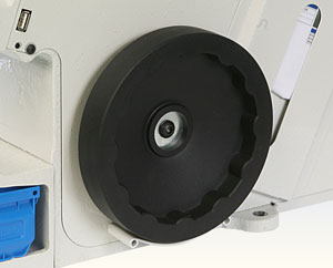
Roue manuelle
La roue manuelle est utilisée pour la réalisation du cycle manuel de centrage de la matrice avant la mise en production. La roue fait le poinçon se déplacer en bas et permet de contrôler le positionnement de l’outil.
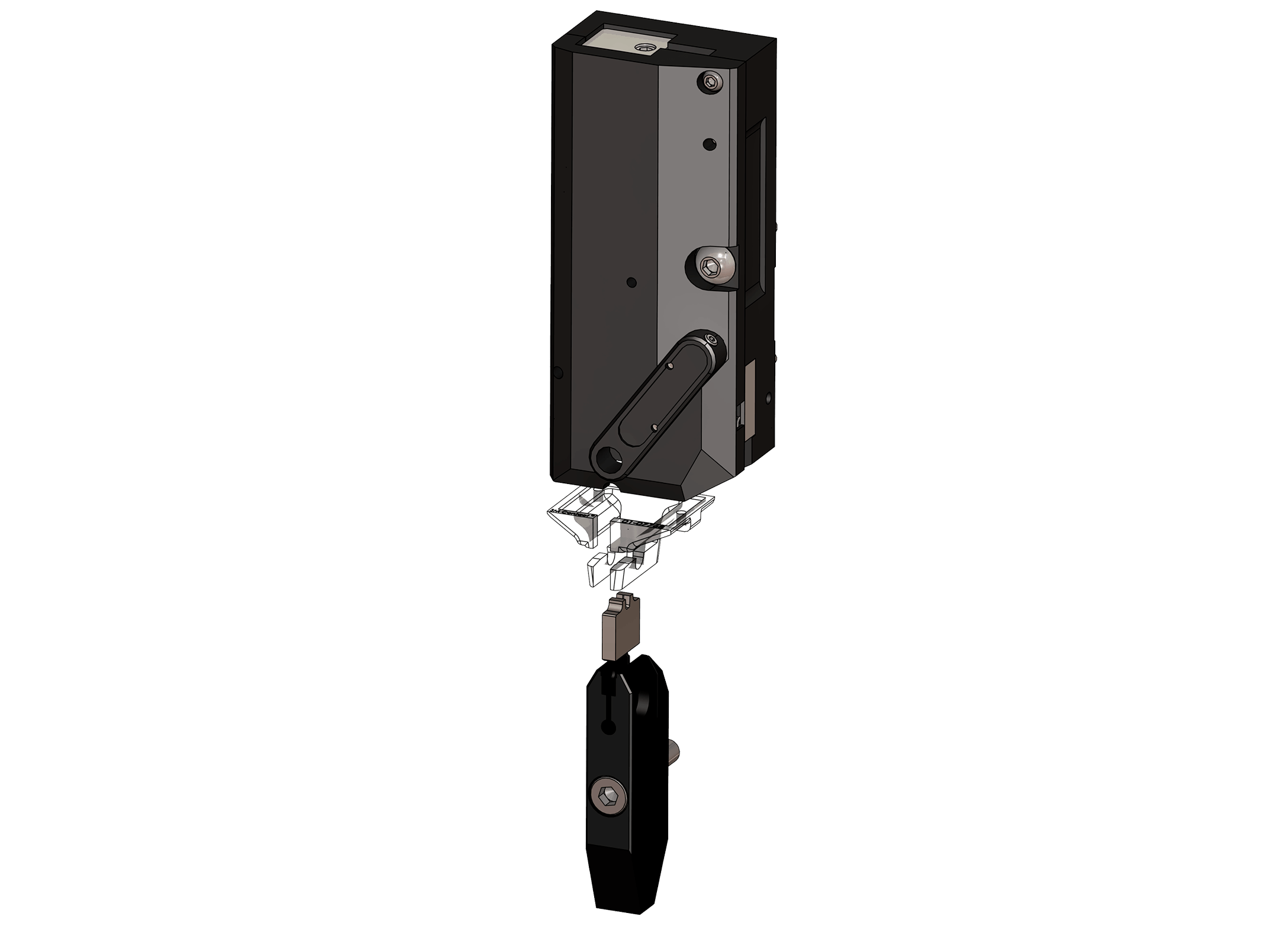
Lot d’outils
Le lot d’outils comprend la matrice, l’enclume, le poinçon, guide de poinçon et le bloc de coupe.
Le type et la dimension de la matrice, la forme du bout du poinçon sont à adapter à chaque connexion.
La surface inclinée de la matrice, la surface coupante lisse, la cassette d’outils à changement rapide et l’ajutage avec éclairage intégré pour la protection des doigts garantissent un travail efficace et sécurisé.
La mémoire interne permet de conserver les paramètres de la connexion, les paramètres recommandés et la liste des pièces de rechange.
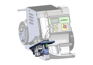
Manual/ automatic fixture
Allows accurate positioning of the components. Fine adjustment of the height position of components. Prevents double crimps in same position. Machine has a sensor detecting jig presence on a fixture.
Manual fixture is moved by operator between loading and work positions manually. Automatic fixture moves between loading and work positions automatically with servomotor.
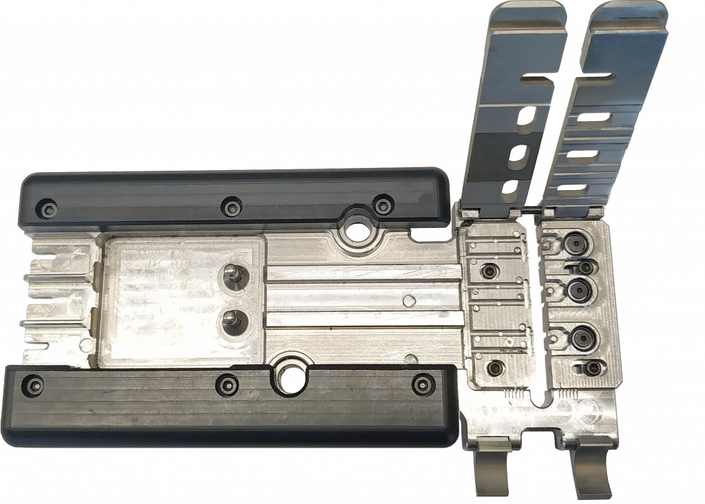
Jig
Removable or build-in part of a fixture that perfectly fits the shape of components and thus allows its precise positioning. If machine has 2 jigs, while one is processing, second can be reloaded by another operator. Jig could be adapted to the components depending on its quantity, shape, materials.
OPTIONS
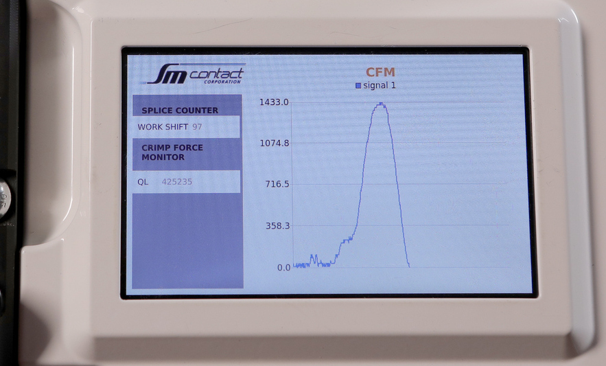
Crimp Force Monitor (CFM)
CFM captures force-time curve and detects any deviation from the quality tolerances. System works with many types of splicing and crimping machines and suites well to any application requiring inline monitoring of forces.
The reference curve of CFM corresponds to crimping force, but in fact it can reflect such quality deviations as: missing wire strands, inaccurate components positioning or crimp height, insufficient insulation strip length, insulation in the splice area, etc.
CFM also allows to adjust automatic cutting and/or rejection of defective items.
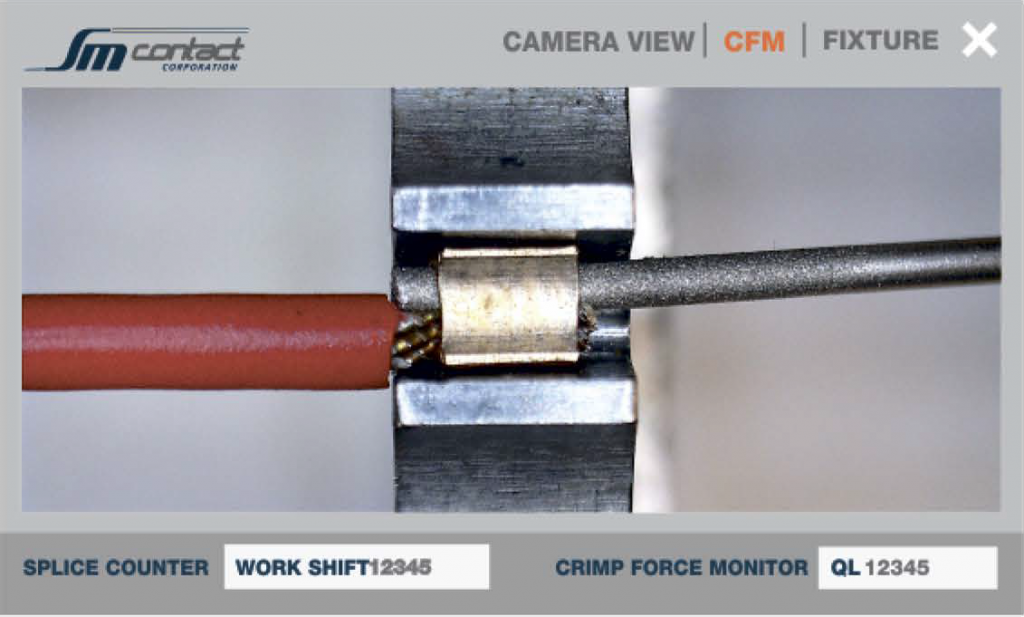
Contrôle vidéo de la position des composants
La caméra intégrée est orientée vers la matrice et transmet l’image en mode de temps réel. De cette façon l’opérateur peut disposer les composants dans la matrice d’une manière plus précise.
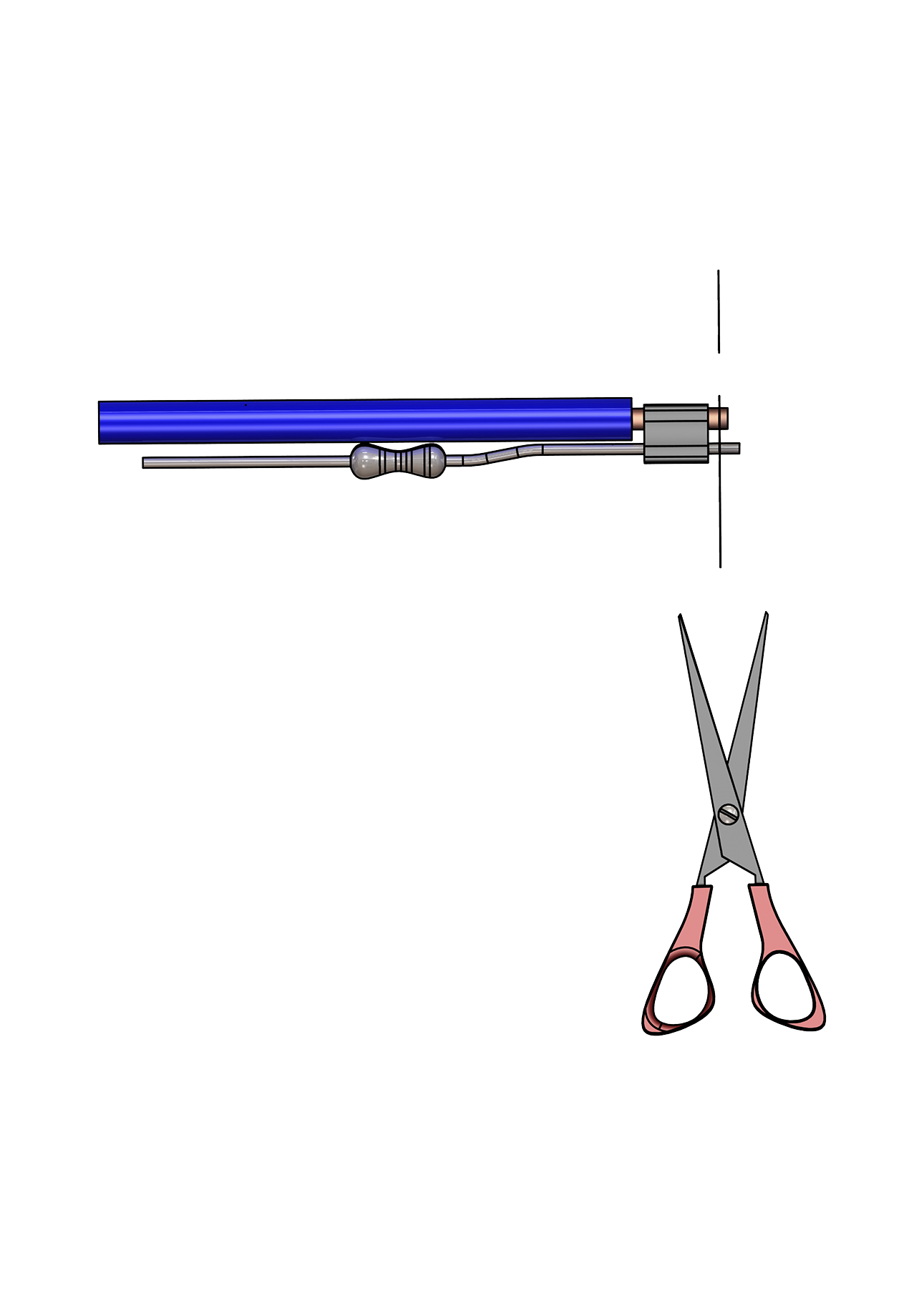
Cutting unit
Cutting unit cuts the components after splice crimping so that their ends protruding out of the splice band from one side are of equal length. It suits wires of up to 1,5 mm2 diameter.
CFM and cutting unit could be integrated to cut defective parts in halves.
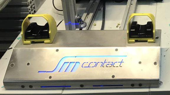
Bimanual cycle start
Requires two hands touch to start the cycle to eliminate hands presence in work zone.

POKA YOKE
Allows controlling utilization of NG/NOK components. If CFM detects quality deviation and estimates connection as NG/NOK, then machine stops operation and waits until NG/NOK component is placed to POKA YOKE bin.

High/ low definition camera
According to the selected program, camera takes picture and controls components` position, color and stripping length. High or low definition is selected depending on size of components.
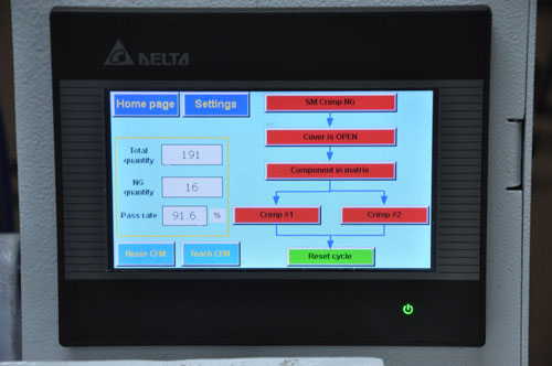
HMI
HMI system shows the complete work algorithm, indicating the current step and step when the failure occurred if any. It can be displayed as an algorithm graphics or product visualization.
HMI provides intuitive process control. It is possible to readjust all the sensors, including CFM to the other product by choosing the corresponding program in the interface. Within password protected area one can switch machine subfunctions on/off.

Frame & cabinet
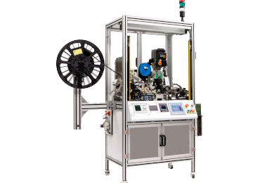
Machine and all its components can be integrated into floor mount frame with PLC and HMI units for operation control.

Lighting & safety beams
Safety beams can be installed on the frame to detect foreign object presence and to stop the machine. This feature as well as work area lighting guarantees operator’s safety.
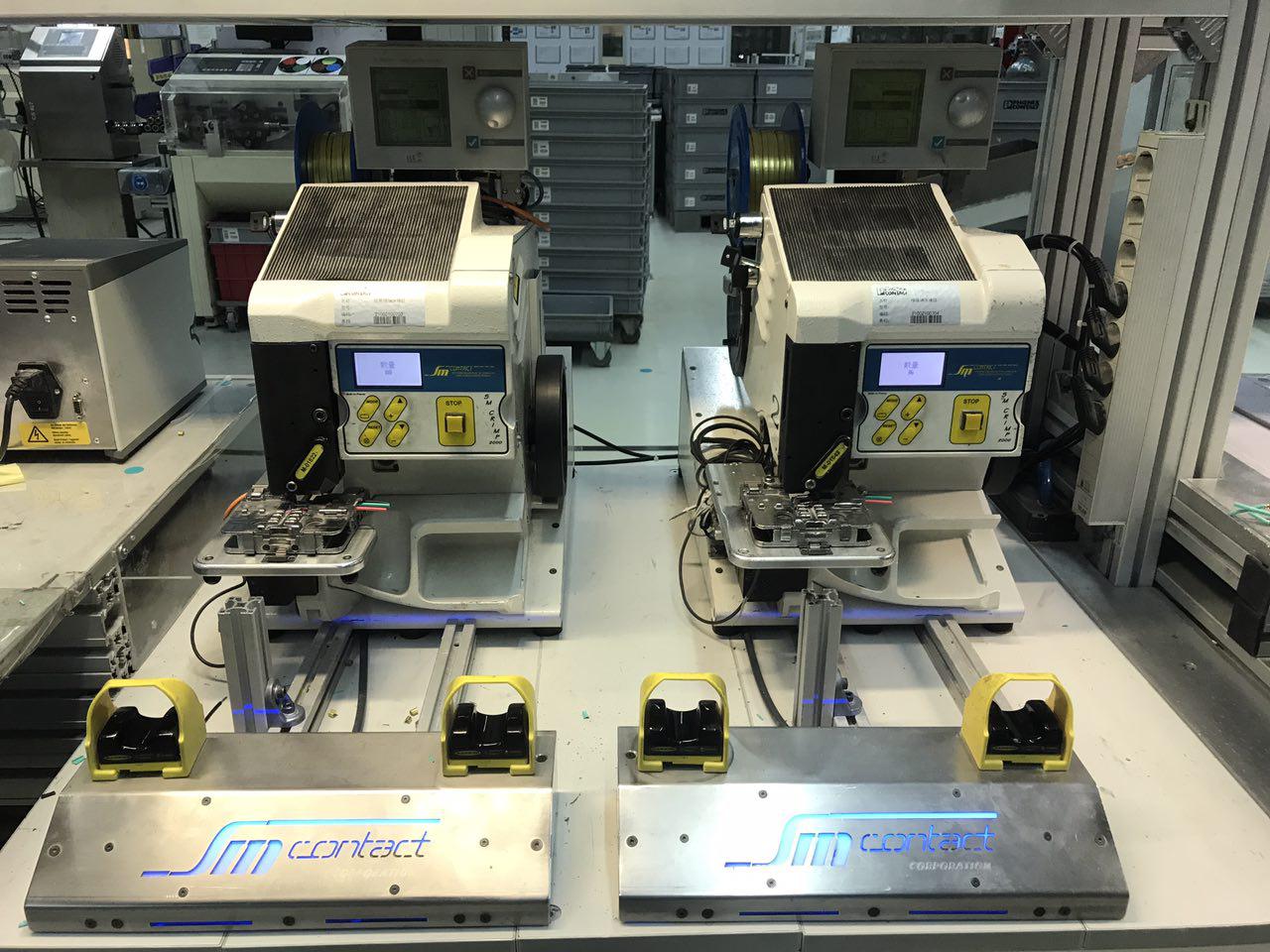
Double crimping
Two machines are used: one set up for one splicing type, another – for the second. This solution makes process faster and perfectly fits if product consists of different sized crimping.
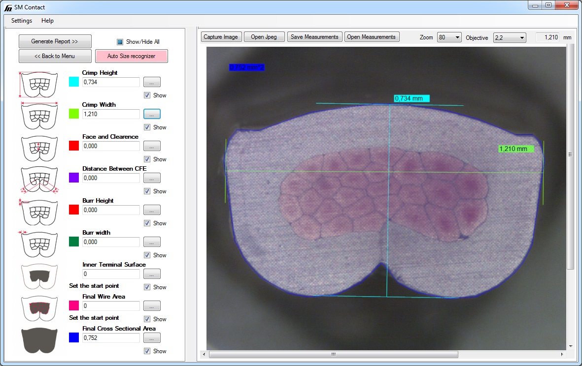
Quality control equipment
Laboratory equipment allows to control whether the splice quality matches industry norms or any other special requirements. Check our micrograph laboratories, pull force and crimp height control tools, as well as specialized measurement software.
ÉNERGIES ALTERNATIVES
AUTOMOBILE
CONSTRUCTION CIVILE
ÉLECTRONIQUE
INDUSTRIE DE LA LUMIERE
BIENS DE CONSOMMATION
MEDECINE
TRANSPORT FERROVIAIRE
CORDS
DIODE & RESISTANCE
FIL FILAMENTAIRE
FIL & CONDENSATEUR
FIL & BOBINE D'INDUCTANCE
FIL & DIODE
FIL & CADRE DE MAINTIEN DES BROCHES
FIL & CIRCUIT IMPRIME
WIRE & METAL TAB
FIL & CAPTEUR
WIRE & METAL TAB
FIL & RESISTANCE
WIRE & METAL TAB
FIL & FIL
WIRE & METAL TAB
CIRCUIT IMPRIME & CONNECTEUR COAXIAL
WIRE & METAL TAB
FIL & PIN
WIRE & METAL TAB
FIL & CONNECTEUR EN PLASTIQUE
WIRE & METAL TAB
FIL & PRISE ELECTRIQUE
WIRE & METAL TAB
WIRE & THERMAL FUSE
WIRE & METAL TAB
ссылки на доп. картинки
0-1
0-2
0-3
0-4
0-5
0-6
1-1
1-2
2-1
3-1
3-2
4-1
4-2
4-3
4-4
4-5
5-1
6-1
7-1
7-2
7-3
7-4
7-5
8-1
8-2
9-1
9-2
9-3
9-4
9-5
9-6
10-1
10-2
10-3
10-4
10-5
10-6
10-7
10-8
10-9
10-10
10-11
10-12
11-1
11-2
11-3
11-4
11-5
11-6
11-7
11-8
11-9
11-10
11-11
11-12
12-1
12-2
12-3
13-1
13-2
13-3
13-4
13-5
13-6
13-7
13-8
13-9
14-1
14-2
14-3
14-4
14-5
14-6
15-1
16-1
16-2
16-3
16-4
16-5
