2019
What is a GOOD crimp connection?
Crimp connection is a gas-tight joint formed by compression between electrical components (most often wires and cables) and a specifically designed crimp termination or splice band. Compressed terminal reshapes all strands in a wire like it is cold-welded to create a low resistance solderless electrical connection.
Correct wire preparation and size, termination type, tooling and setting provide a reliable connection. The first step of crimp quality evaluation is to measure its cross section.
| Cross section measured parameters | |
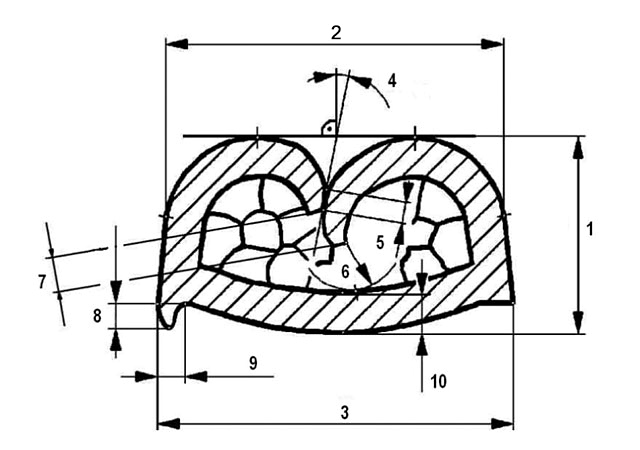 |
1 Crimp height 2 Crimp (tangent) width 3 Crimp width 4 Support angle 5 Support height 6 Barrel end clearance 7 CFE distance between crimp barrel ends 8 Burr height 9 Burr width 10 Splice/Base thickness |
 |
11 Inner terminal surface |
 |
12 Final wire area |
 |
13 Final cross section area |
 |
14 Strands quantity |
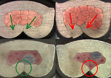
Acceptable and unacceptable wire connections
| Tight closure | |
 |
 |
| Minimum seam, all wire strands are contained inside crimp “ears” | Connection when strands can appear not fully encapsulated in the crimp results in less mechanical strength and stability. The other concerns when crimp wings touch crimp “floor” |
| Connection symmetry | |
 |
 |
| Crimped “ears” formed uniformly | Compression when strands are not evenly distributed may cause lower electrical performance and mechanical secureness |
| Compression | |
 |
 |
| Wire strands deformed into honeycomb pattern with minimum evident voids | Under-compressed wire strands and voids lead to deterioration of resistance and corrosion |
| Components positioning | |
 |
 |
| Fine conductivity, physical integrity of components | Improper components distribution, under-compressed strands and gaps influence electrical conductivity and durability |
| Burrs (“cat ears”) | |
 |
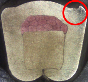 |
| Minimum material extrusion on corners | If a crimp wing curl gets broken off, it may cause short-circuit |
| Cracks in splice band | |
 |
 |
| No signs of fracturing in corners | Cracks |
Crimp quality industrial standards
Replying to a question whether the crimp is proper or bad, it is appropriate to turn to quality norms. They have been developed and are widely applied in many industries, particularly in the automotive. For example, manufacturers of automotive components simply do not order a connection from a company that does not comply with corresponding standards.
The standards are based on mechanical and accelerated environmental tests duplicating potential operating conditions which a connection can experience through the expected automobile life cycle. They make demands to components and their dimensions, compacting (compression) rate and contact resistance.
Such standards as PSA 9634115099, VW 60330, USCAR-21, TDK-EPCOS F61207-R3308, Bosch N42AP 730 (2014), TYCO and Renault cover only multi-stranded cables and crimp barrels, that is cable to terminal standard electrical crimps.
Exotic materials (aluminum, steel, fiber, etc.) and components (battery tab, PCB pin, sensor, etc.) are considered in few norms providing that the supplier is in charge of defining reference criteria. To specify optimal parameters of such connection one should use IEC 60352-2 norms giving test schedules and techniques.
IEC 60352-2 test schedules and techniques
According to IEC 60352-2, it’s necessary to perform one of the following test algorithms depending on materials and components types:
1) Basic test schedule for connections conforming to all requirements given in the standard: made with stranded wires of 0.05-10 mm2 cross section or solid wires of 0.25-3.6 mm diameter with copper or copper alloy (content min. 60% of copper) terminals; wires made of annealed copper and quite less plastic one, having 10% elongation before break;
2) Full test schedule covers all components and materials, including exotic ones, that don’t fully conform to all of the requirements. Connections made with solid wires, nickel, steel, stainless steel or materials exceeding the tensile strength of 600 MPa may be used.
The Basic test schedule entails just pull out force test on 20 samples and 20 cycles of current loading on another 20 samples while the Full test schedule requires pull out force test on 16 samples, an intensive current loading test (500 cycles!) on 8 samples and climatic tests, including rapid change of temperature and climatic sequence (dry heat, damp heat, cold) on 16 samples.
Obtained results are to be compared with target values giving in corresponding IEC norms such as pull out force and contact resistance graphs. It’s worth mentioning that the latest comes with coefficient values for different barrel materials.
Equipment for connection quality evaluation
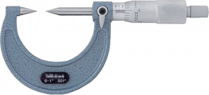
| Crimp height measurement | ||
| Caliper | Micrometer | Digital crimp measurement tool |
 |
 |
 |
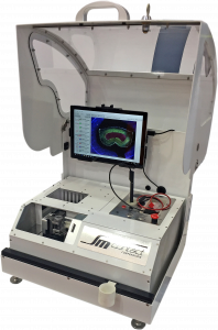
| Cross section analysis | Pull out force test |
| Micrograph laboratory – to cut connection and perform visual assessment of its cross section | Motorized pull force tester – to check that connection has sufficient mechanical strength |
 |
 |